VYPER
™
VARIABLE SPEED DRIVE
OPERATION
100-210 IOM (JUL 09)
Page 43
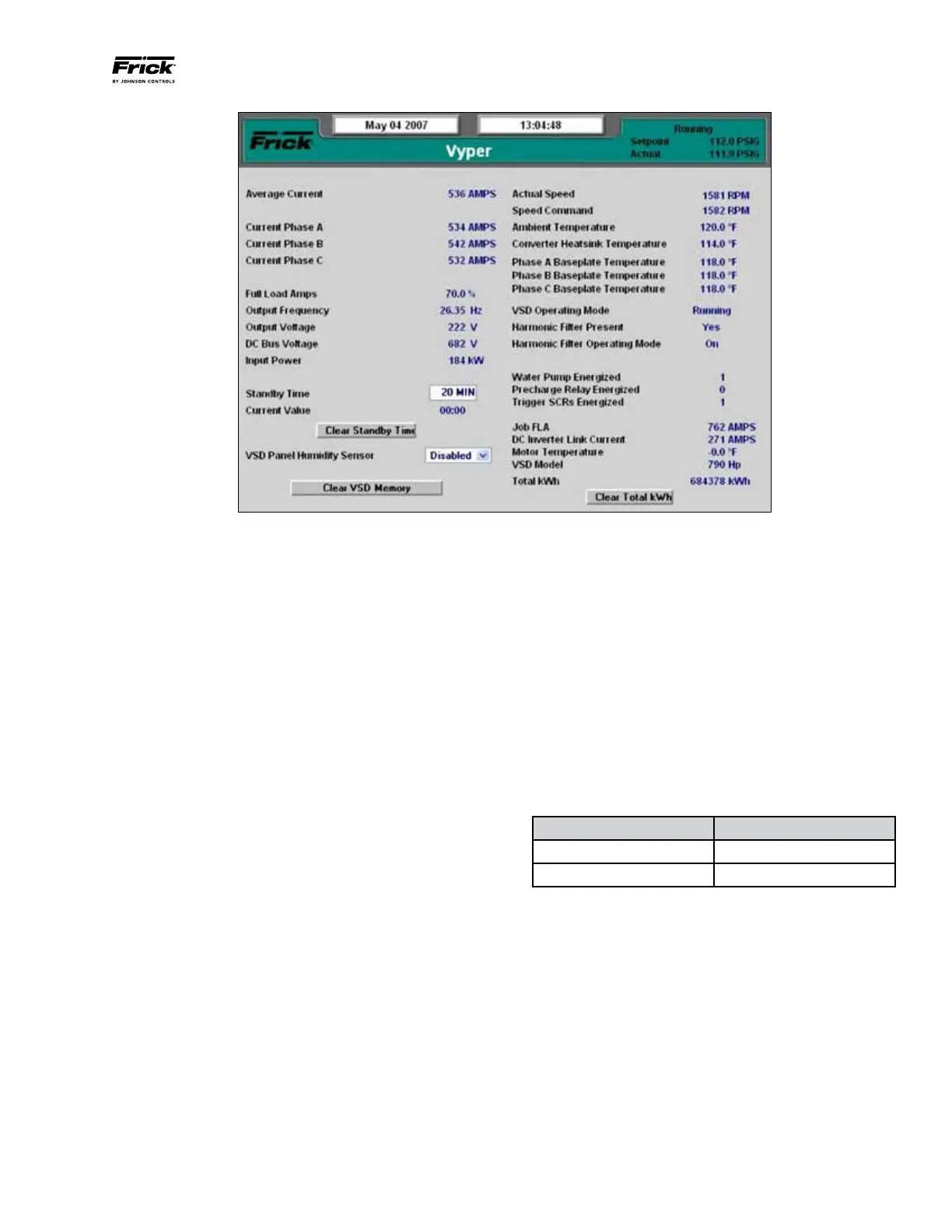
Figure 43 - Vyper™ Screen
VYPER SCREEN SETPOINTS
The Vyper
™
Screen (See Figure 43) contains setpoints and
information pertinent to the operation of the Vyper
™
such as
internal currents, voltages, and temperatures. This screen also
gives detailed information on some external equipment such
as the circulation pump and the motor temperature.
The Service Level 2 Vyper
™
Screen is similar to Level 1, but
adds the capability of adjusting several setpoints, as follows:
Standby Time: The VSD enters Standby mode when there
is no load on the VSD. The VSD capacitor banks remain
charged and the compressor output is 0 Hz. Standby mode
permits fast acceleration when the load returns. If the time
of zero load surpasses the Standby Time setting, the VSD
will need to go through a restart sequence. The values for
Standby mode can be set from 20 to 120 minutes.
Clear Standby Time: This option can be pressed to clear the
Standby time value from the VSD if not desired.
Clear VSD Memory: Clear the existing trending values in
the Vyper
™
memory.
Clear Total kWh: This function clears the accumulated kWh
totals from the counter since the last reset. The value returns
to zero upon selecting this option.
The following Vyper
™
screen parameters display measured
values in accordance with the user defined unit selections.
• AverageCurrent(Amps)
• CurrentPhaseA(Amps)
• CurrentPhaseB(Amps)
• CurrentPhaseC(Amps)
• FullLoadAmps(%)
• OutputFrequency(Hz)
• OutputVoltage(Volts)
• DCBusVoltage(Volts)
• InputPower(kW)
• CurrentValueTimer(Min:Sec)
• ActualSpeed(RPM)
• SpeedCommand(RPM)
• AmbientTemperature(°For°C)
• ConverterHeatsinkTemp(°For°C)
• BaseplateTemperature(°For°C)
• JobFLA(Amps)
• DCInverterLinkCurrent(Amps)
• MotorTemperature(°For°C)
• VSDModel(305or435)
• TotalkWh(kWh)
The status of the following parameters are indicated using a
binary number next to the field description. Table 14 describes
the status of the parameter indicator.
Indicator Status
“0” no /off
“1” yes / on
Table 14 – Binary Parameter Indicator Status
• VSDOperatingMode
• HarmonicFilterPresent
• HarmonicFilterOperatingMode
• WaterPumpEnergized
• PrechargeRelayEnergized
• TriggerSCRsEnergized
NOTE: Repetitive/Unexplained Vper Cutouts - For repeti-
tive or unexplained cutouts, tab to the [Clear Standby
Time] button and clear by pressing the enter button.
Repeat that process to also clear the [Clear VSD Memory]
and [Clear Total KWH] buttons.