VYPER
™
VARIABLE SPEED DRIVE
OPERATION
100-210 IOM (JUL 09)
Page 44
HARMONIC FILTER SCREEN
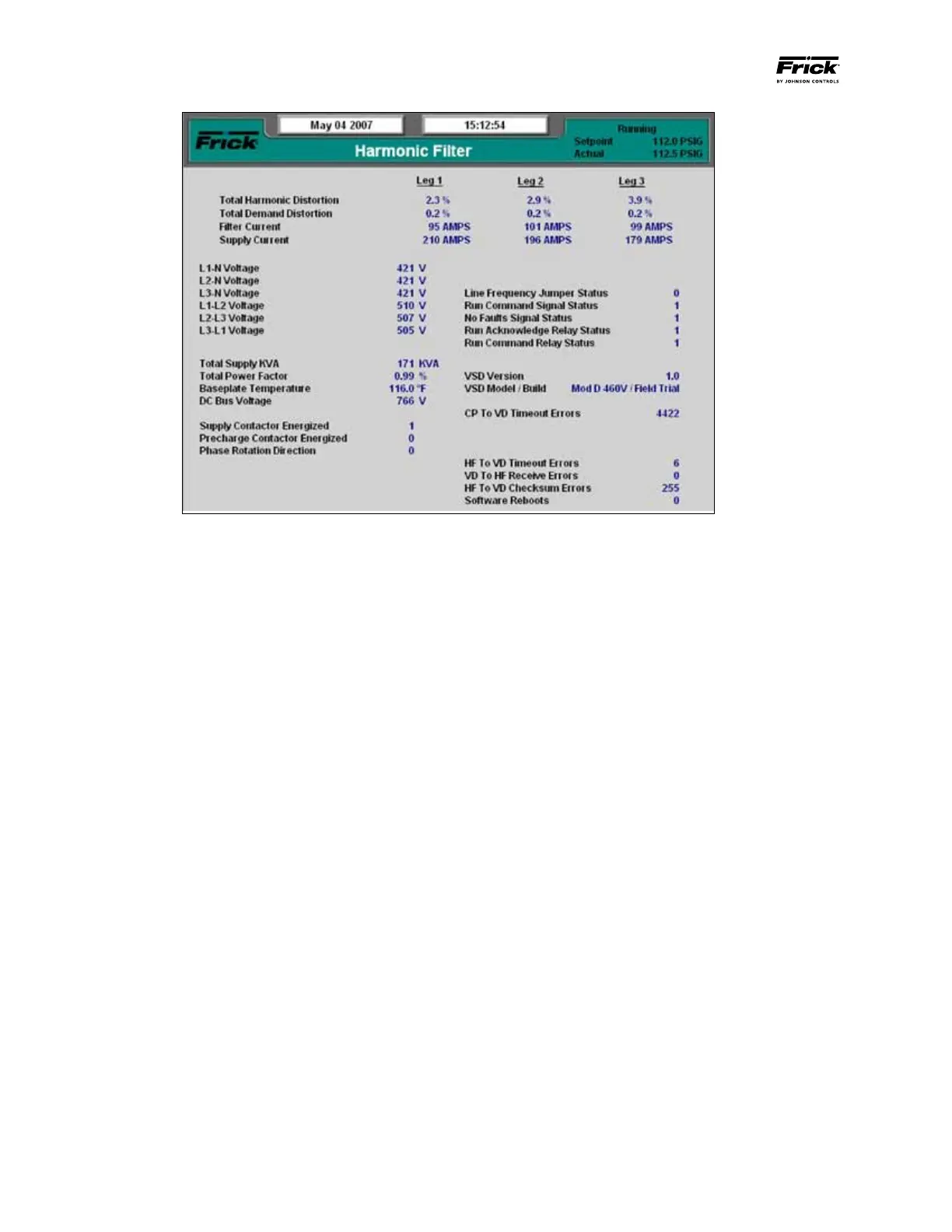
The Harmonic Filter screen (See Figure 44) shows important
aspects of the IEEE519 Harmonic Filter in action. In addi-
tion to current and voltage information the Harmonic Filter
Screen also provides the important measure of current Total
Harmonic Distortion (THD).
All IEEE 519 Harmonic filter parameters are displayed on
this page. This information is useful to obtain the status,
operating conditions and diagnostic information for the
Harmonic Filter.
The following parameters display a real value based on the
displayed units:
• TotalHarmonicDistortionLeg,1,2,3(%)
• TotalDemandDistortionLeg1,2,3(%)
• FilterCurrentLeg1,2,3(Amps)
• SupplyCurrentLeg1,2,3(Amps)
• VoltagesL1-N,L2-N,L3-N,
• L1-L2,L2-L3,L3-L1(Voltage)
• TotalSupplykVA(kVA)
• TotalPowerFactor(%)
• BaseplateTemperature(°For°C)
• DCBusVoltage(Volts)
• ManualSpeedSwitchStatus(RPM)
Figure 44 - Harmonic Filter Screen
The status of the following parameters are indicated using a
binary number next to the field description (See Table 16).
• SupplyContactorEnergized
• PrechargeContactorEnergized
• PhaseRotationDirection(0-ABC,1-CBA)
• AutomanualSwitchStatus
• LineFrequencyJumperStatus
• RunCommandSignalStatus
• NoFaultsSignalStatus
• RunAcknowledgeRelayStatus
• RunCommandRelayStatus
The following parameters display a count or version in whole
numbers.
• InterfaceBoardVersion
• VSDVersion
• ModbusNodeID
• IBTransmitErrors
• CPtoIBTimeoutErrors
• VDtoIBTimeoutErrors
• IBtoVDReceiveErrors
• VDtoIBChecksumErrors
• HFtoIBTimeoutErrors
• VDtoHFReceiveErrors
• HFtoIBChecksumErrors
• Softwarereboots