VYPER
™
VARIABLE SPEED DRIVE
INSTALLATION
100-210 IOM (JUL 09)
Page 34
ADDING AND REPLACING COOLANT
Irritant! Coolant is an irritant.
Always wear eye protection when
servicing the Vyper
™
cooling
system. Failure to do so may result in serious personal
injury.
The shipping fluid must sabe drained
from the
Vyper
™
cooling system
at
installation of drive and replaced with
new system running coolant. Failure to do so may result in
damage to the
Vyper
™
cooling system.
NOTE: Follow all Environmental Protection Agency (EPA)
and local guidelines for disposal of the
Vyper
™
shipping
fluid and coolant.
NOTE:
As part of preventative maintenance and for
proper operation, replace the coolant in the cooling
system once per year. The Frick part number for a one
gallon container of coolant is 013-02987-000.
The Vyper
™
is shipped from the factory with a premixed
shipping fluid containing a rust inhibitor that prevents corro-
sion of the internal cooling passages. The shipping fluid also
helps to keep the internal passages free from contaminants.
The illustration in Figure 26 shows the cooling circuit of a
remote-mounted water-cooled Vyper
™
. The cooling circuit for
the glycol-cooled version is identical.
Figure 26 - Coolant Circulation System
Prior to starting the Vyper
™
for the first time, drain and replace
the shipping fluid from the Vyper
™
cooling system with new
running coolant appropriate for the type of system the Vyper
™
is equipped with. Perform the steps in the following procedure
to replace or add coolant to the system.
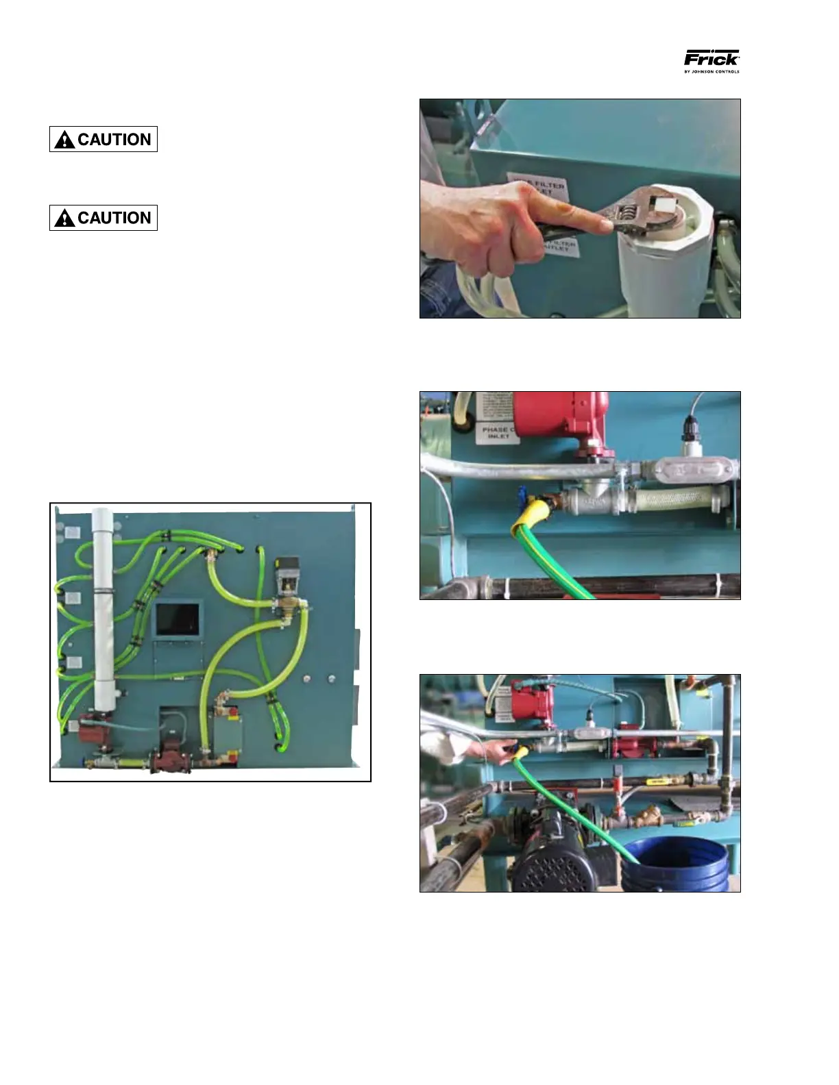
Step 1: (See Figure 27) Disconnect power from the VSD.
Remove the pipe plug from the top of the exit manifold with
an adjustable wrench. This allows air to enter the system
and displace the fluid during draining.
Figure 27 - Removing the Cooling System Pipe Plug
Step 2: (See Figure 28) Connect a hose fitting to the drain
of the heat exchanger. Be sure that the hose is connected
tightly to the drain fitting so no fluid is spilled.
Figure 28 - Hose connected to the Heat Exchanger Drain
Step 3: (See Figure 29) Open the drain valve and allow the
fluid to drain from the loop. Catch buckets should be able to
hold approximately 4 gallons of liquid.
Figure 29 - Draining Coolant