VYPER
™
VARIABLE SPEED DRIVE
INSTALLATION
100-210 IOM (JUL 09)
Page 29
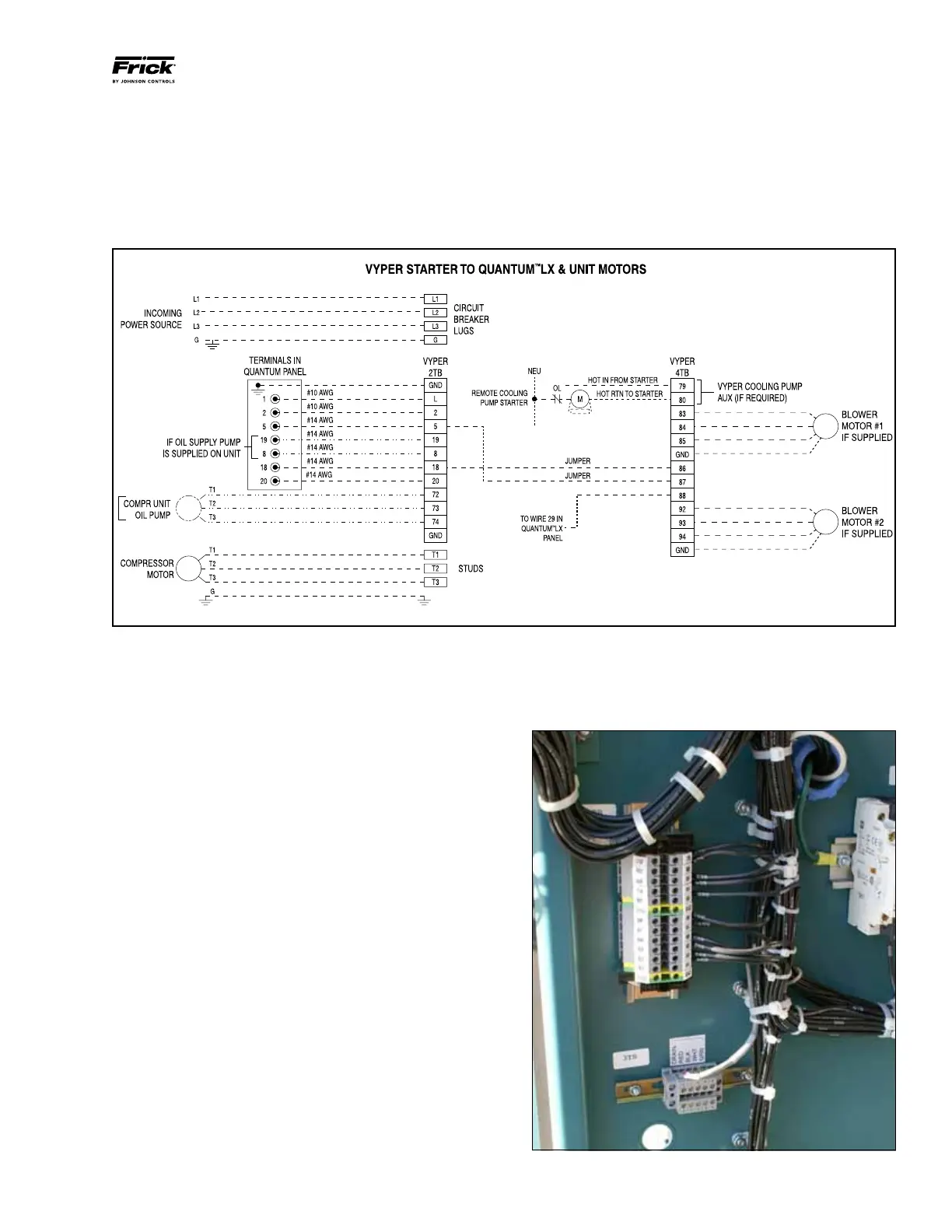
Figure 20 - Vyper
™
Starter, Motor, Blower, and Quantum Wiring
VYPER
™
WIRING AND WIRING DIAGRAMS
Figures 20 through 25 provide the wiring terminations for the
Frick Vyper
™
Drive. These drawings illustrate the necessary
connections required to install the unit.
Always refer to the wiring diagrams included inside the
Vyper
™
cabinet to ensure the unit is wired following the most
up-to-date version of the wiring diagram.
QUANTUM
™
LX COMMUNICATIONS WIRING
The picture in Figure 21 shows the junction points for the
Quantum
™
LX panel control wiring into the Vyper
™
cabinet.
This wiring location is in the lower left corner of the Vyper
™
cabinet. The control wiring enters the Vyper
™
cabinet from
the left side cabinet wall through a connection port.
Figure 21 - Quantum
™
LX Communications Terminal Block