VYPER
™
VARIABLE SPEED DRIVE
INSTALLATION
100-210 IOM (JUL 09)
Page 35
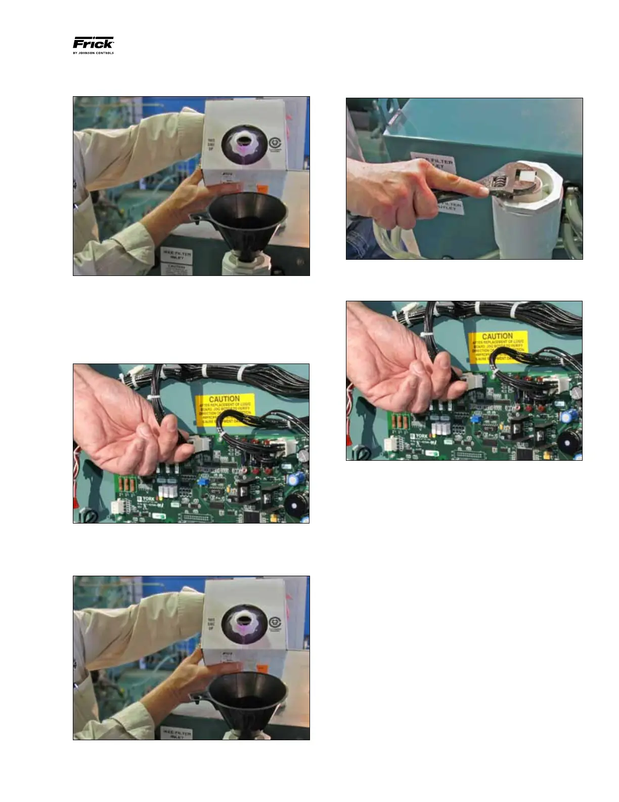
Step 4: (Figure 30) Close the drain valve and refill the cooling
system with the new coolant.
Figure 30 - Refilling the Cooling System
Step 5: (Figure 31) Apply power to the VSD unit and locate
the Logic Board found on the inside of the cabinet.
Unplug
J2, which will manually power the cooling pump to run and
circulate the coolant throughout the system. Allow the pump
to run (at least 5 minutes) until all trapped air is purged from
the coolant system.
Figure 31 - VSD Logic Board Connection J2
Step 6: (Figure 32) Top off the cooling system until the fluid
level remains constant about one inch (25 mm) from the top
of the manifold.
Figure 32 - Topping Off the Coolant Supply
Step 7: (Figure 33) Replace and tighten the plug on the top
of the manifold using an adjustable wrench.
Figure 33 - Installing the Cooling System Pipe Plug
Step 8: (Figure 34) Insert plug J2 into the logic board to stop
the coolant pump.
Figure 34 - VSD Logic Board Connection J2