VYPER
™
VARIABLE SPEED DRIVE
MAINTENANCE
100-210 IOM (JUL 09)
Page 59
VYPER
™
ALARMS / SHUTDOWNS
OVERVIEW
In addition to the Alarms and Shutdowns that the Quantum
™
LX
software generates for the basic compressor package,
there are warnings and shutdowns that are associated with
the Vyper
™
drive operation. These can be initiated by the
Quantum
™
LX panel or the Vyper
™
drive. The following pages
describe these warnings and shutdowns by title and descrip-
tion as well as the cause and items to check.
When a Shutdown occurs, the display backlight will flash on
and off to alert an operator of the shutdown. This visual alarm
will help get the attention of the operator in a noisy engine room
environment where audible alarms may not be heard. Pressing
any key on the keypad will clear the flashing backlight alarm.
The FRICK VYPER
™
FAULT CODES table shows the full list-
ing of fault codes. A detailed description and troubleshooting
recommendations follow.
The following warnings and or shutdowns are initiated by
the Quantum
™
LX panel. These safeties are set for When
Running:
High Motor Stator Temp. – If the motor stator temperature
rises above a critical point, one or more embedded thermistors
will open, removing the digital input to the Dig. Aux. #1 module,
wire #28 (typical). There is one thermistor per winding.
If the motor is equipped with stator RTDs (one per winding)
the same result will occur only that the signal is now an analog
signal and is set up as one of the PHD monitoring channels.
The warning and shutdown values can be seen on the PHD
setpoints screen of the
Quantum
™
LX panel and should be
set based on the limits of the motor’s insulation class.
Blower Motor Aux. – If the motor is equipped with auxiliary
blowers mounted to the top of the main drive motor, then a
confirmed run signal is required. This signal is in the form of
a digital signal from the Aux. Contacts of the blower motor
starter/s and is received by Dig. Aux. #2, wire #29 (typical).
High Vyper Coolant Temp. – The Vyper Coolant Temp. is
monitored by the
Quantum
™
LX Panel from a temperature
probe mounted at the coolant reservoir on analog auxiliary
#9 (Ch. 13 analog brd #2). If the Vyper
™
Coolant exceeds
the High Temp Warning or Shutdown values for the delays,
this warning or shutdown will occur. These values can be
seen on page 2 of the Analog Auxiliaries setpoints screens.
Default settings are 130°F for the warning, 135°F for the
shutdown.
Low Vyper Coolant Temp. – The Vyper Coolant Temp. is
monitored by the
Quantum
™
LX Panel from a temperature
probe mounted at the coolant reservoir on analog auxiliary
#9 (Ch. 13 analog brd #2). If the Vyper Coolant exceeds the
Low Temp Warning or Shutdown values for the delays, this
warning or shutdown will occur. These values can be seen on
page 2 of the Analog Auxiliaries setpoints screens. Default
settings are 85°F for the warning, 80°F for the shutdown.
NOTE: If the compressor has been down for an extended
period and the ambient temperature is less than the Low
Vyper Coolant Temp. warning or shutdown values, it may
be necessary to lower these settings temporarily in order
to get the drive running.
This setpoint can never be set
lower than 5° F above ambient dry
bulb temperature. If not sure of dry
bulb temperature, DO NOT GUESS.
Once the drive is running with the coolant temperature back
above the default setting for this safety, go back and change
them to 85°F for the warning and 80°F for the shutdown.
The warnings and shutdowns on the following pages are
initiated by the Vyper
™
drive and communicated to the
Quantum
™
LX panel for display and clearing purposes.
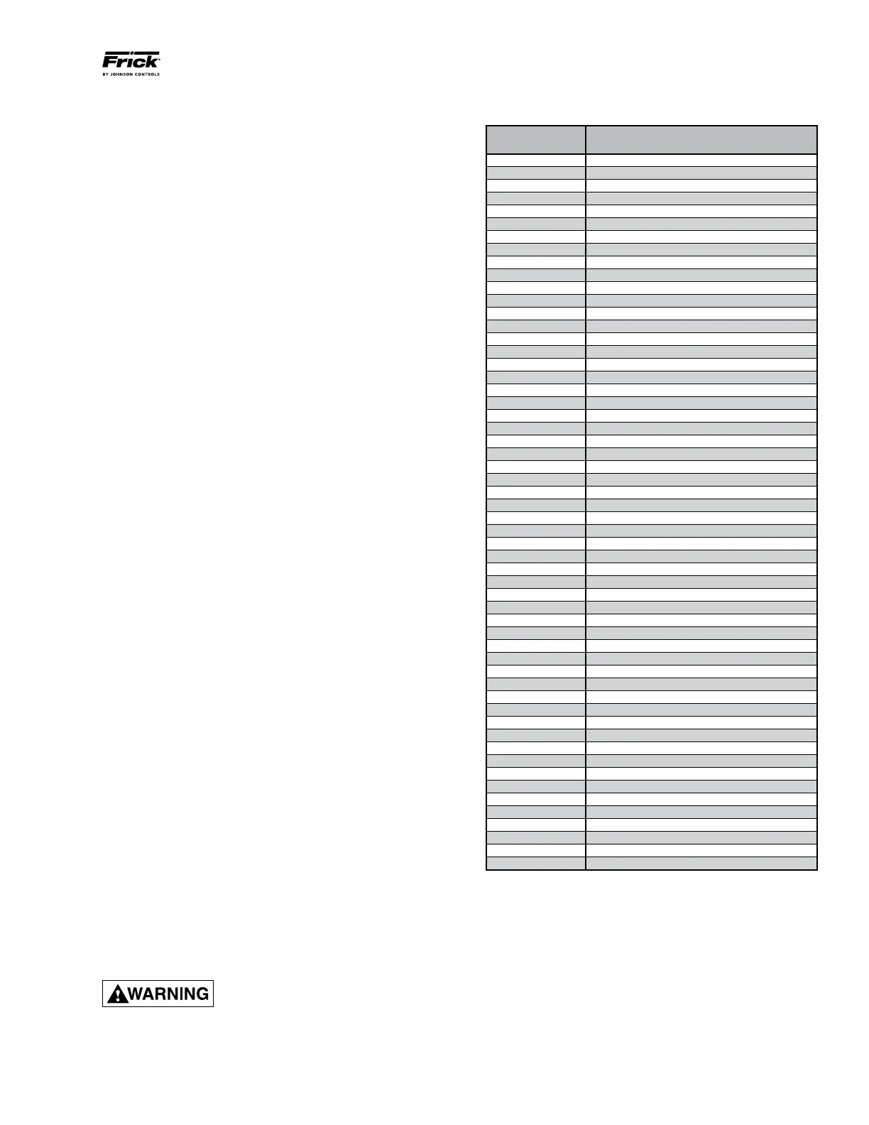
FRICK VYPER
™
FAULT CODE LIST
Quantum
™
LX
Fault Code
Quantum
™
LX Fault Message
1 VSD Interface Board Power Supply Fault
3 VSD Interface Board Motor Current > 15%
4 VSD Interface Board Run Signal Fault
5 VSD Interface Board to Panel Comms Loss
7 VSD Initialization Fault
8 VSD Stop Contacts Fault
9 Harmonic Filter Logic Board Or Comms Fault
10 Harmonic Filter High Total Demand Distortion
11 VSD High Phase B Inverter Baseplate Temp
12 VSD High Phase C Inverter Baseplate Temp
13 VSD Low Phase B Inverter Baseplate Temp
14 VSD Low Phase C Inverter Baseplate Temp
17 VSD High Phase A Instantaneous Current
18 VSD High Phase B Instantaneous Current
19 VSD High Phase C Instantaneous Current
21 VSD Phase A Gate Driver Fault
22 VSD Phase B Gate Driver Fault
23 VSD Phase C Gate Driver Fault
24 VSD Single Phase Input Power Fault
27 VSD 105% Motor Current Overload Fault
28 VSD High DC Bus Voltage Fault
29 VSD Logic Board Power Supply Fault
33 VSD Low DC Bus Voltage Fault
34 VSD DC Bus Voltage Imbalance Fault
35 VSD High Internal Ambient Temp Fault
36 VSD High Phase A Inverter Baseplate Temp
37 VSD Logic Board Processor Fault
38 VSD Run Signal Fault
39 VSD High Converter Heatsink Temp Fault
40 VSD Invalid Current Scale Selection
41 VSD Low Phase A Inverter Baseplate Temp
42 VSD Serial Communication Fault
43 VSD Precharge Lockout Fault
44 VSD Low Converter Heatsink Temp Fault
45 VSD Current Imbalance Fault
46 VSD Precharge - DC Bus Voltage Imbalance
47 VSD Precharge - Low DC Bus Voltage 2
48 VSD Precharge - Low DC Bus Voltage 1
50 Harmonic Filter High DC Bus Voltage Fault
51 Harmonic Filter High Phase C Current Fault
52 Harmonic Filter High Phase B Current Fault
53 Harmonic Filter High Phase A Current Fault
54 Harmonic Filter Phase Locked Loop Fault
56 Harmonic Filter Logic Board Power Supply
65 Harmonic Filter Precharge - High DC Bus Voltage
66 Harmonic Filter Precharge - Low DC Bus Voltage
67 Harmonic Filter DC Current Transformer 1
68 Harmonic Filter DC Current Transformer 2
69 Harmonic Filter High Baseplate Temp Fault
71 Harmonic Filter Low DC Bus Voltage
75 Harmonic Filter DC Bus Voltage Imbalance
76 Harmonic Filter 110% Input Current Overload
77 Harmonic Filter Run Signal Fault
81 VSD Interface Board NovRAM Failure
83 Harmonic Filter Serial Communication
84 Harmonic Filter Input Frequency Out of Range
Table 20 - Fault Code List