VYPER
™
VARIABLE SPEED DRIVE
OPERATION
100-210 IOM (JUL 09)
Page 45
PROGRAMMING THE MOTOR SCREEN
The various portions of the Motor Screen require program-
ming in order to control the compressor motor and Vyper
™
.
Some fields require calculations to program the proper set-
points. Advance to the Motor Screen by pressing the [MENU]
key and then selecting “Setpoints” and “Drive”. Program each
section as follows:
Nameplate (See Figure 46)
Refer to the motor nameplate for the information to enter
in fields of the Motor Screen “Nameplate” section. These
fields are for reference only and are not setpoints that control
operation.
Use the cursor arrow and [Tab] keys to navigate between
setpoints. Use the keypad to program the specifications listed
on the motor nameplate. Press the [Enter] key to accept the
value for each field.
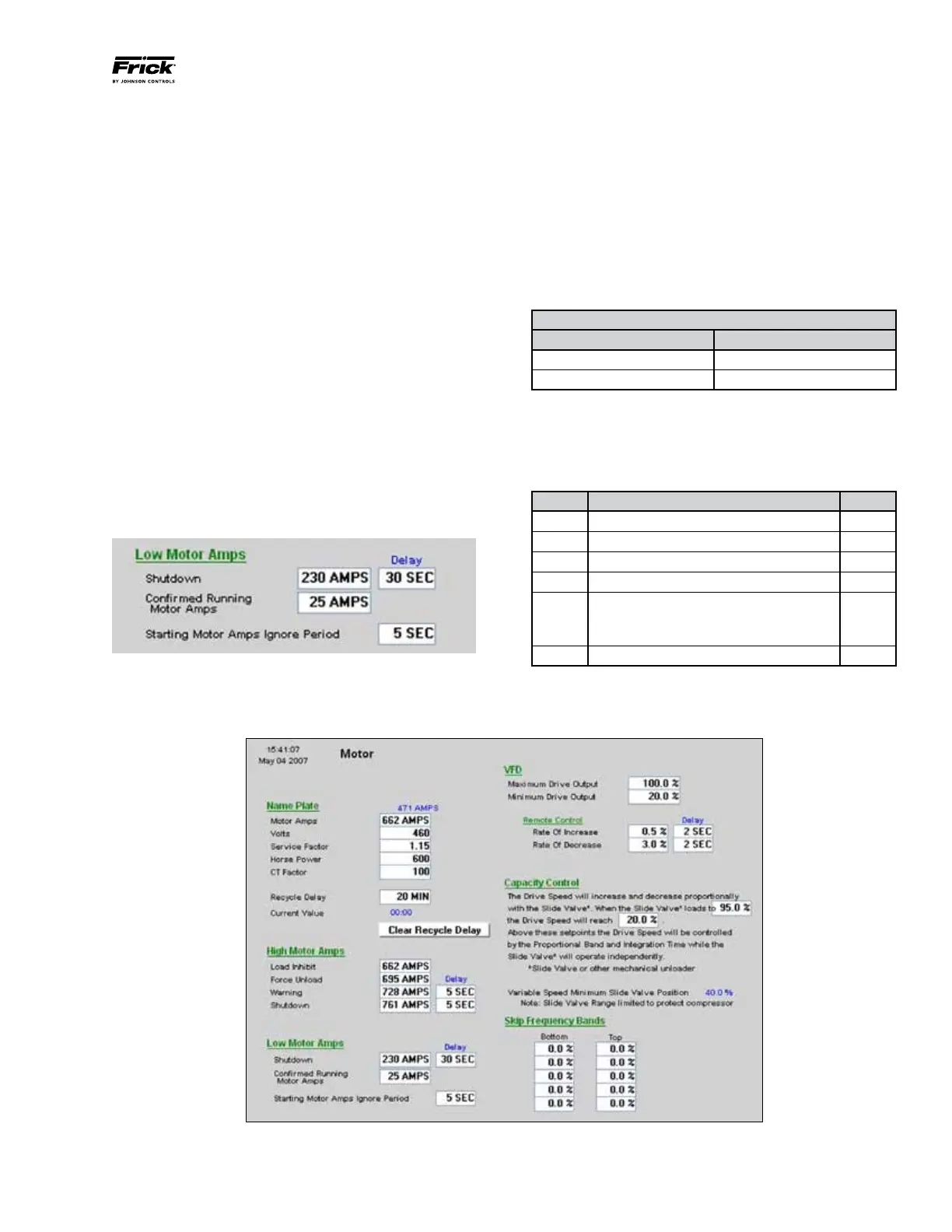
Low Motor Amps (See Figures 45 and 46)
Program each of the values for the “Low Motor Amps” as
shown in Figure 45. These values may be altered in accor-
dance with job requirements.
Use the cursor arrow and [Tab] keys to navigate between
setpoints. Use the keypad to program the specifications listed
on the motor nameplate. Press the [Enter] key to accept the
value for each field.
Figure 45 - Low Motor Amps
High Motor Amps (See Figures 46 and 47)
The setpoints in “High Motor Amps” section of the Motor
Screen are critical to protect the compressor motor and drive
from damage due to excessive current.
The operator calculates the values for these setpoints using
the formulas in Tables 15 through 18.
Step 1: (See Table 15) Determine the “Applied Motor Full
Load Amps (FLA)” to be used for High Motor Amp setpoints.
Use the Service Factor listed on the motor nameplate to
determine the Applied Motor FLA. Use the calculated value
in Table 16.
“Applied Motor FLA” Calculation
IF USE
Service Factor = 1.0 Mtr Nameplate FLA / 1.15
Service Factor = 1.15 Mtr Nameplate FLA
Table 15 – Applied Motor FLA Calculation
Step 2: (See Table 16) There are several safety scenarios
regarding the compressor motor and Vyper
™
Drive. Perform
the calculations in Table 16 to determine which strategy is
applicable to the motor and Vyper
™
Drive at the job site.
Line Parameter Value
1 Applied Motor FLA (Table 15)
2 Applied Service Factor 1.15
3 Multiply (Line 1 x Line 2)
4 HP rating of Vyper Drive
5 Vyper Amp Limit
If Line 4 is 700/572 HP, value is 880 A
If Line 4 is 912/752 HP, value is 1180 A
6 Multiply Line 5 x 1.05
Table 16 – High Motor Amps Safety Calculation Table
Figure 46 - Motor Screen