112
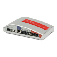
Connect all lines of the new hybrid plug
(9) (TX 20) – 3.8 Nm
Place the cover plate (10) on the hybrid
plug (8) and secure it using TX 20
screws (11) – 3 Nm
Install the busbar (5) and secure using
TX 25 screws (6) – 2.5 Nm
Insert the ribbon cable (7), connect and
lock it
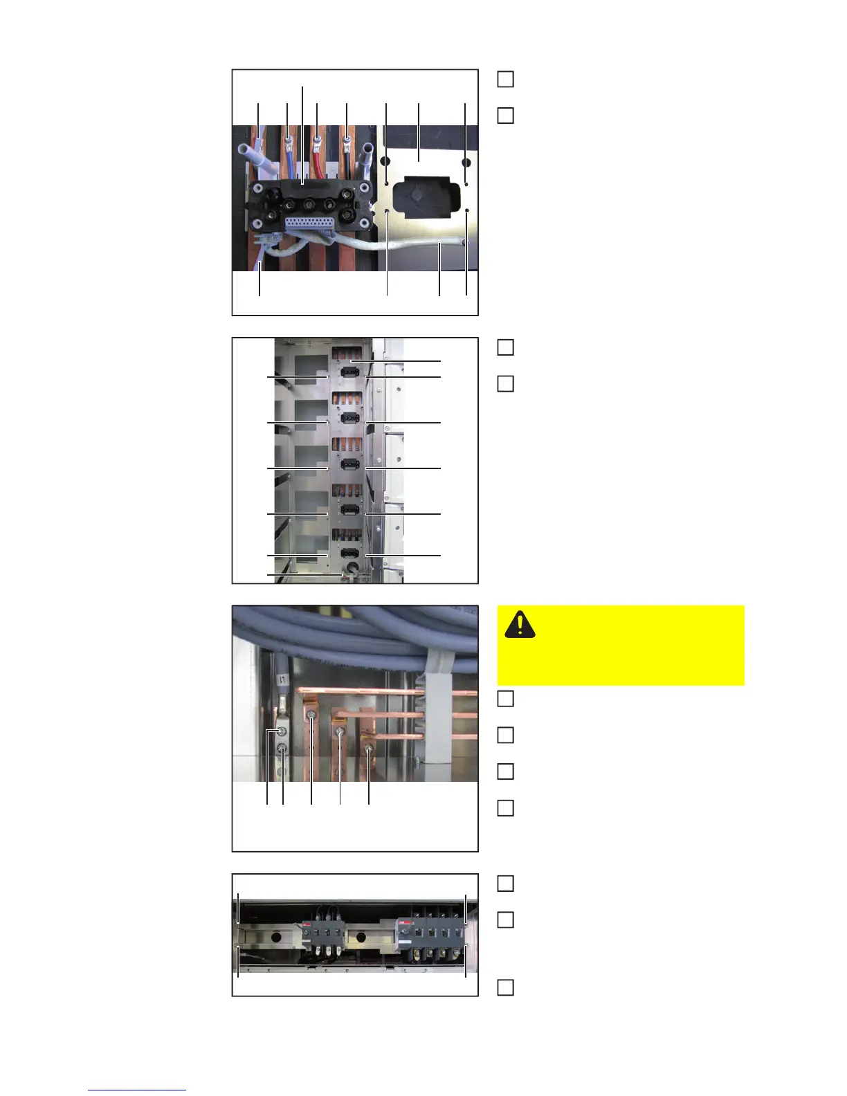
Connect cable (copper busbars) (4) (5
x TX25x16mm) – 4 Nm
Reinsert all removed power stage sets
into the inverter
Install the securing plates of the power
stage sets
Install power stage set spare plate on
Fronius CL 36 / 48
Install the main switch rails and secure
using 4 TX 25 screws (3) – 2.5 Nm
Connect all lines from the AC and DC
main switches (or AC contactor) (see
"Installing AC main switches" and "In-
stall DC main switches")
Secure cover plate with 3 TX 25
screws (3) – 2.5 Nm
(8)
(9)
(9)
(9) (11) (11)(9)
(9) (9)
(10)(11) (11)
2
3
(6) (6)
(5)
(6) (6)
(6) (6)
(6) (6)
(6) (6)
(7)
4
5
(4)(4) (4) (4) (4)
CAUTION! Short circuit danger
Only use original screws to con-
nect the cables (copper busbars)
(4). Screws must be no longer
than 16 mm.
6