126
Electrical Tests
PE Conductor Re-
sistance
The PE conductor resistance test is to be carried out with the cabinet doors open.
- Ensure that the device to be tested is safely disconnected from the AC mains. The grid
leads (L1, L2, L3, N) must not be connected. Observe safety rules.
- Ensure that the device to be tested is safely disconnected from the DC mains. DC ca-
bles must not be connected. There may be a DC voltage in the cables. Follow safety
rules.
- During the measurement, all switches, controls, etc., must be closed.
- AC protection and DC main switch must be activated.
- The module grounding (if present) must be removed from the inverter during the in-
spection.
- Disconnection is required from SolarNet and Datcom Ring.
1 Measuring instrument
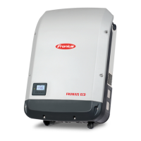
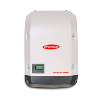
2 Inverters
9 Measuring leads
Example: Measurement of the ground conductor re-
sistance
(1) Ground terminal
(2) Example measurement point.
- Measurements are taken between the ground terminal (1) of the device and each
touchable, conductive part connected with the ground conductor (e.g. 2).
- The resistance must not exceed 0.3 Ω *)
*) These requirements relate to DIN VDE 0701-0702 and ÖVE/ÖNORM E8701-1. In addi-
tion, individual national requirements and standards must also be observed.
 Loading...


