13 SEP 12
/ Battery Charging Systems / Welding Technology / Solar Electronics
G
GG
G
H
HH
H
E
EE
E
F
FF
F
D
DD
D
I
II
I
J
JJ
J
F
FF
F
C
CC
C
J
JJ
J
D
DD
D
D
DD
D
A
AA
A
1
11
1
10
1010
10
2
22
2
3
33
3
4
44
4
9
99
9
8
88
8
5
55
5
D
DD
D
C
CC
C
7
77
7
D
DD
D
6
66
6
11
1111
11
B
BB
B
D
DD
D
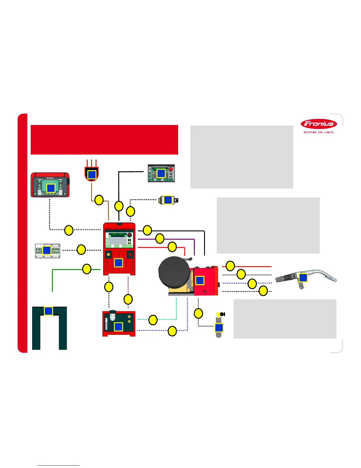
Components consist of
-
--
-1
11
1-
--
- Power Source
-
--
-2
22
2-
--
- Wire Feeder
-
--
-3
33
3-
--
- Torch
-
--
-4
44
4-
--
- Work Surface/Fixture
-
--
-5
55
5-
--
- Main Power (230 or 460V AC⁄
-
--
-6
66
6-
--
- Front Panel
-
--
-7
77
7-
--
- Gas Tank
-
--
-8
88
8-
--
- Remote Control Unit (RCU⁄
-
--
-9
99
9-
--
- Robot Interface
-
--
-10
1010
10-
--
- Cooler
-
--
-11
1111
11-
--
- PC Interface Tool
Component Layout
Weld System
Component Management
Controlled by LocalNet (Fronius communication
protocol⁄.
Plug and play configuration
Provides both operating power and
communication to peripheral components.
Connections consist of
-
--
-A
AA
A-
--
- Ground Connection
-
--
-B
BB
B-
--
- Main Power (230 or 460V AC⁄
-
--
-C
CC
C-
--
- Gas
-
--
-D
DD
D-
--
- LocalNet
-
--
-E
EE
E-
--
- Motor Voltage (55V DC⁄
-
--
-F
FF
F-
--
- Main Current
-
--
-G
GG
G-
--
- Pump Voltage (230 or 400V AC⁄
-
--
-H
HH
H-
--
- Data Lines (non LocalNet⁄
-
--
-I
II
I-
--
- Coolant Out
-
--
-J
JJ
J-
--
- Coolant In
-
--
- 3
3 3
3 -
--
-