169
8.4 Power supply
8 Electrics/electronics
MITSUBISHI FUSO body/equipment mounting directives for FE Issue date: 20. 10. 2020
! Only print out complete sections from the current version
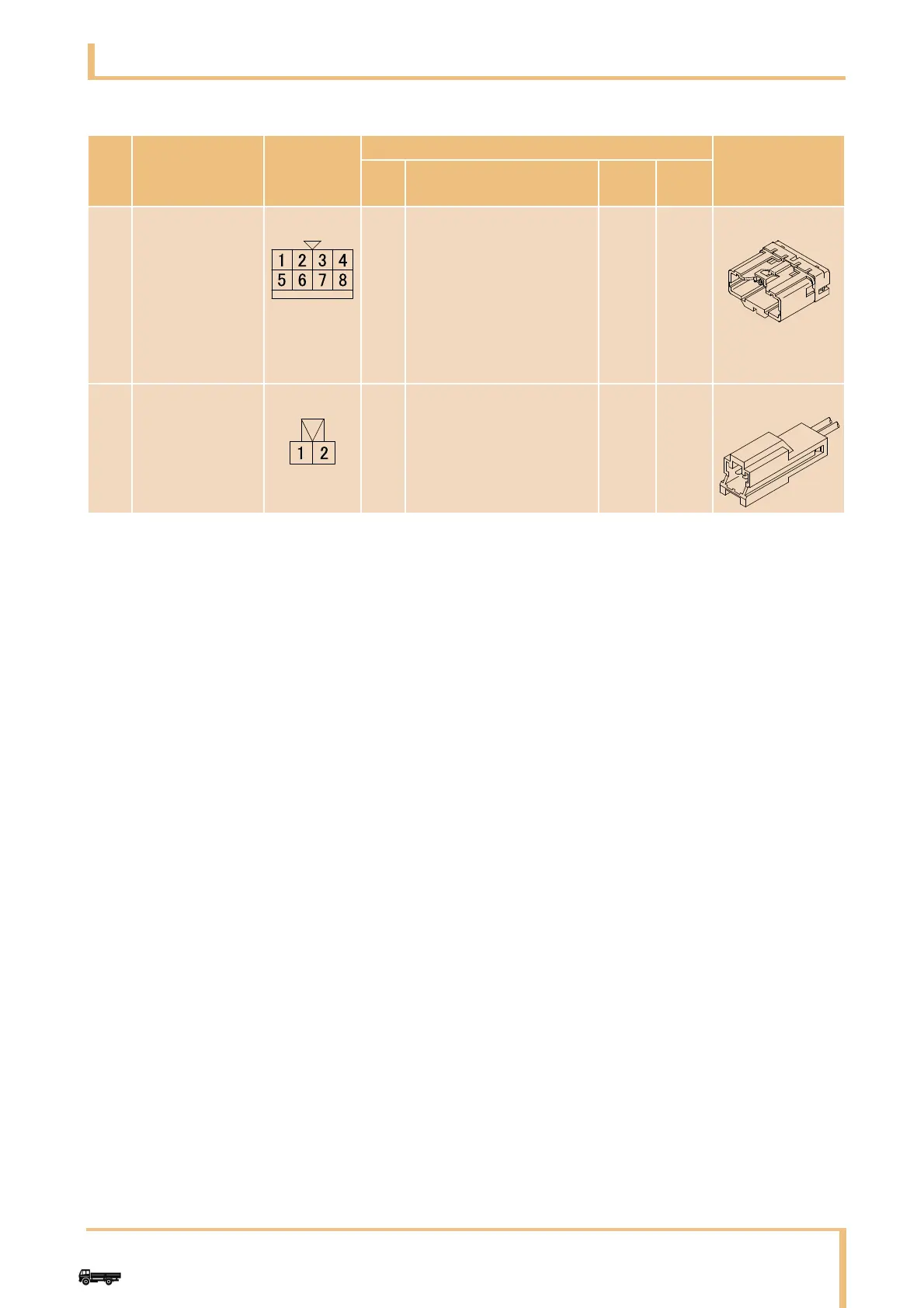
-: The connector marked with - is used for signal cabling only, not used to connect the loads.
*1: Loads to be connected to the connector marked with *1 should be arranged so that the total value of the
connector output in each of the cab and chassis side shall not exceed the permissible current.
No. Part Name
Connector
No.
Circuit Description
Mating Connec-
tor
No. Circuit
Line
color
Load
B OPTION
CONNECTOR
(Only When sub
harness
(MK649751) is
arranged)
MH052847 01
02
03
04
05
06
07
08
PARKING ON (24V/12V)
NEUTRAL (24V/12V)
PTO (24V/12V)
ILL (24V/12V)
MAIN (24V/12V)
GND
BATT (24V/12V)
ACC (24V/12V)
Br
R-G
Lg-R
O-B
L-R
B
G-R
W-R
*1
*1
*1
*1
*1
10A
*1
*1
MH052805
C OPTION
CONNECTOR
MH056867 01
02
IDLE UP (SWtoGND) R-B - MH056800