46
4 Technical threshold values for planning
4.6 Vehicle body incline
MITSUBISHI FUSO body/equipment mounting directives for FE Issue date: 20. 10. 2020
! Only print out complete sections from the current version
4.6 Vehicle body incline
As far as possible, take steps to ensure that the weight
of the body-building part is balanced in the left-right
direction. If it is not possible to ensure left-right weight
balance, carry out adjustment by adding a
counterweight or adding a spacer to the mounting
frame, for example.
When carrying out body-building work, be sure to
observe the following items in order to ensure that the
vehicle does not topple over or become twisted.
• Be sure to carry out the work on flat ground.
• As far as possible, carry out the work with both the
front and rear tires on the ground.
• When installing the body, ensure that the chassis is
horizontal.
• When installing the body, place it symmetrically on
the chassis to prevent it from tilting.
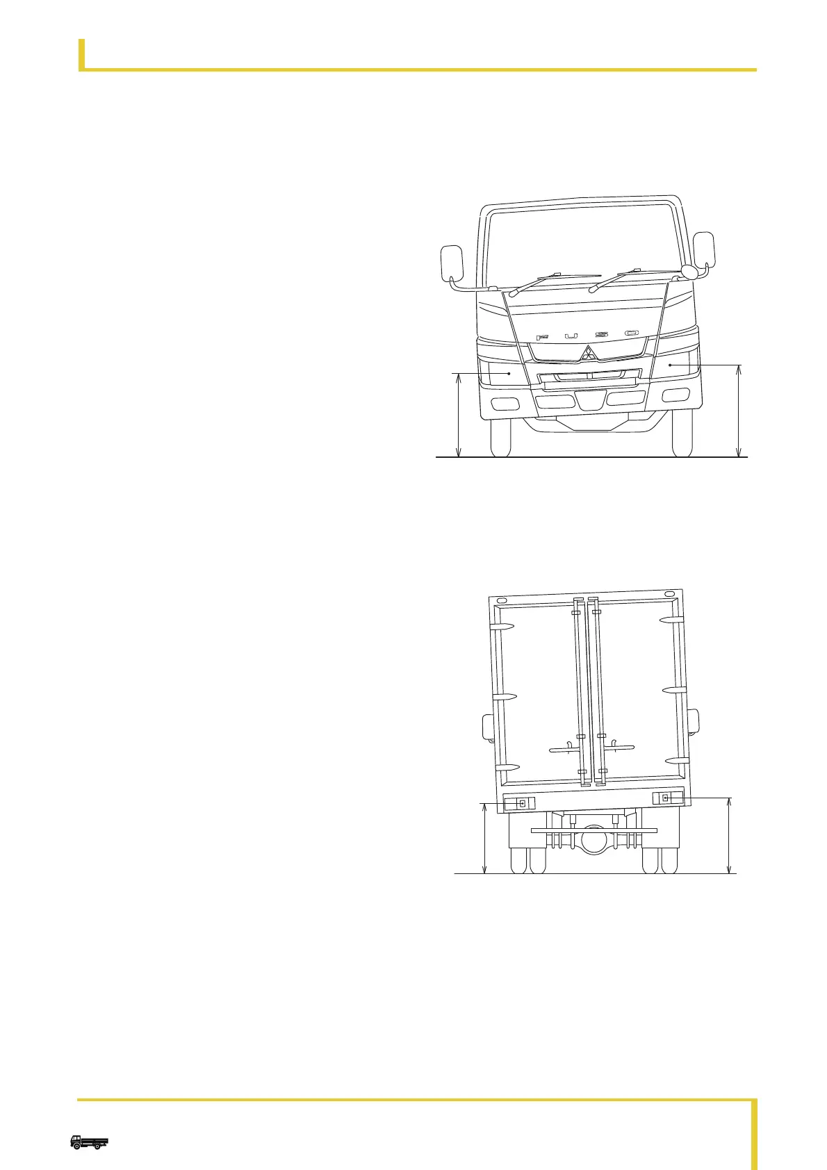
4.6.1 Measuring the tilt of the body
When carrying out body-building work, measure the
tilt of the body shown below. If the tilt of the body of
the completed vehicle when empty exceeds the target
value, correct it.
•Front tilt: ΔHf
Left-right difference at the headlamp center height
ΔHf = H1 – H2
Target: | ΔHf |
≤ 10 mm
•Rear tilt: ΔHr
Left-right difference at the stop lamp center height
ΔHr = h1 – h2
Target: | ΔHr |
≤ 10 mm
• Twisting in the longitudinal direction of the vehicle:
Tw
Tw = ΔHf – ΔHr = (H1 – H2) – (h1 – h2)
Target: | Tw |
≤ 10 mm
H1 Right front
H2 Left front
h2 Left rear
h1 Right rear
N60.00-2258-00
H1
H2