8A089X01 Rev 1
SLIM Installation Manual
3/23/2018 Page 55 of 61
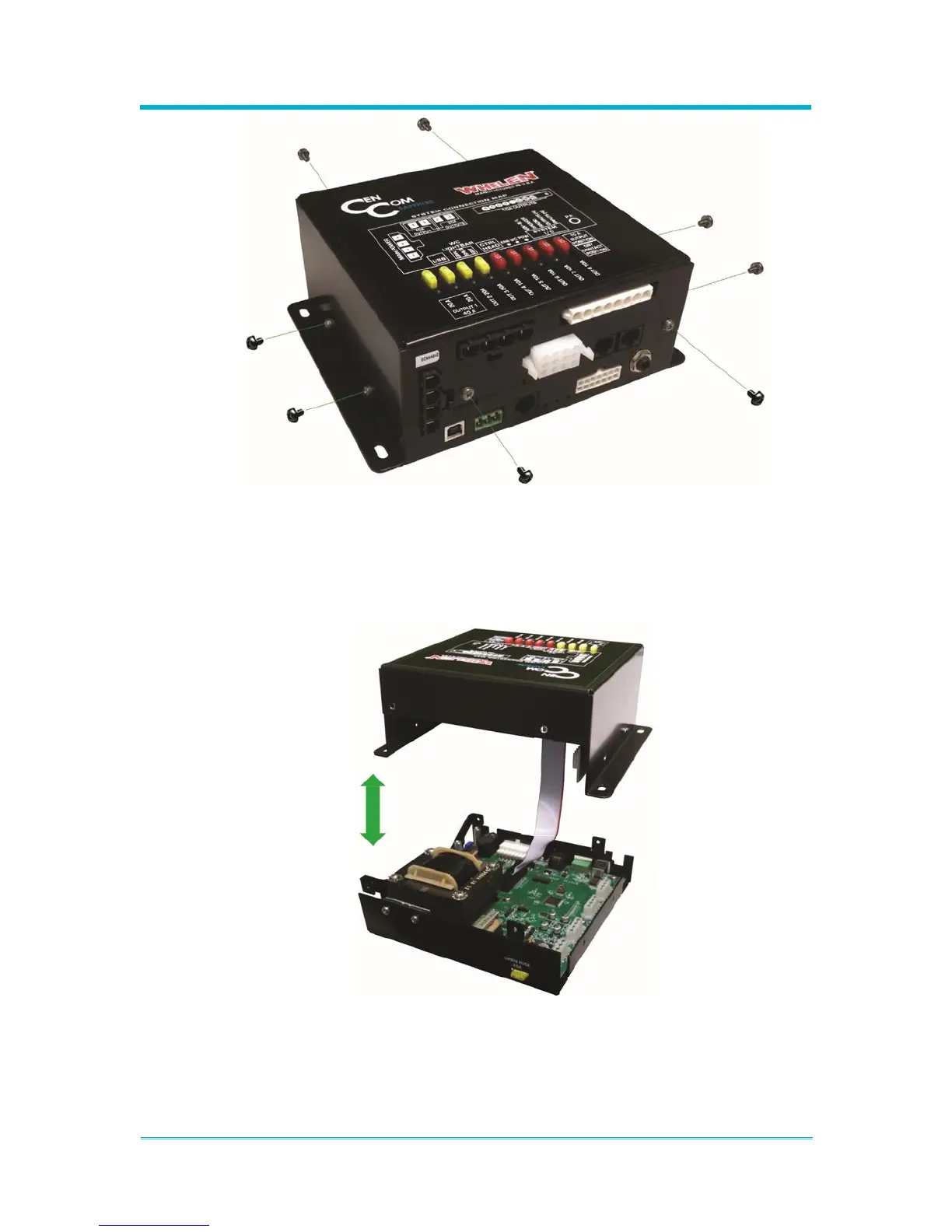
2. Separate the enclosure by carefully pulling apart the top and bottom pieces. Note
that there will be a ribbon cable connecting the two halves. This cable can be gently
removed from either piece while working or left connected if the pieces are left
close enough together. If the cable is removed, ensure it is reconnected with the
same orientation after installing the expansion board.
3. Once you have gained access to the bottom internal board of the amplifier, verify
that extension jackscrews (spacers) are installed in the proper location. If
traditional screws are currently installed then replace them with the extension
jackscrews – the existing screws will then be used to secure the expansion board.
See the image below for proper installation location. When installing the expansion