8A089X01 Rev 1
SLIM Installation Manual
3/23/2018 Page 56 of 61
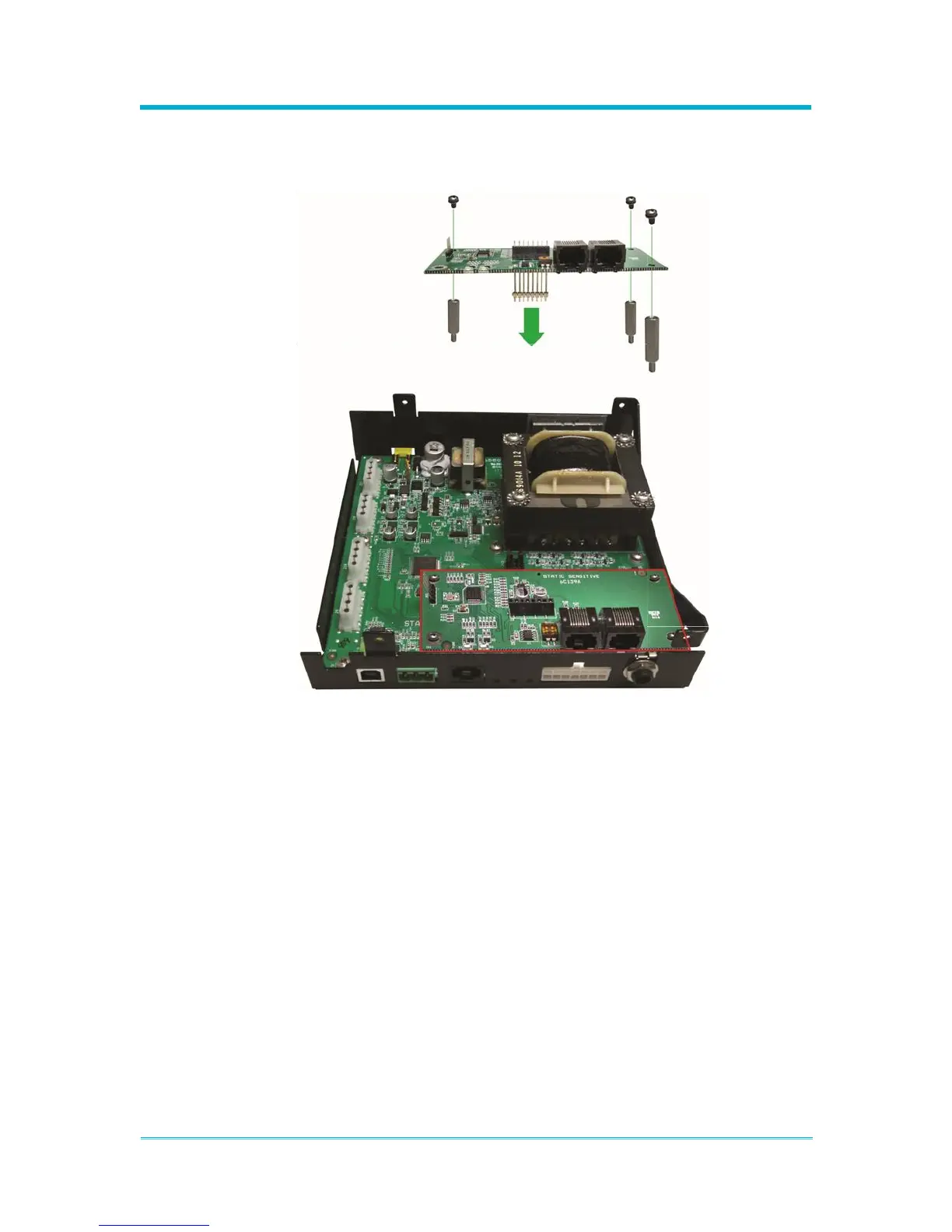
board ensure that the short side of the 8 position header pin row is inserted into
the bottom amplifier board and that the long side of the header pin row is inserted
correctly through the expansion board sockets.
4. Once the header pin row and expansion board are installed correctly and secured
to the amplifier, reassemble the siren enclosure. If the cable connecting the top
and bottom amplifier boards was removed during installation, ensure it is
reconnected. Remember to re-secure the amplifier enclosure together using the
six external screws.