Operators and Technicians Manual
2011 – 2014 FutureLogic, Incorporated. All Rights Reserved. MNL Page 12 04/10/2014
MNL-000067 REV.X03
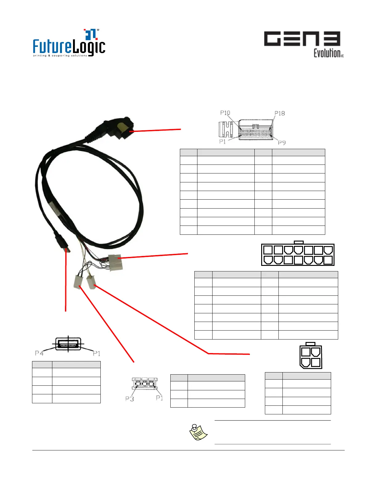
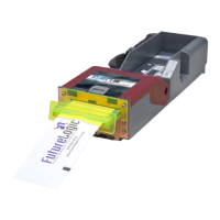
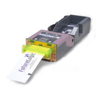
USB/RS232 Interface Cable
The Interface Cable connects the printer through the Base Port and to the machine through the RS232
Power/ COMM Connector (14-pin).
There are three additional connectors to which connection is optional: USB, Auxiliary Bezel, and Auxiliary
Comm Port (RS232).
Figure 5-3 USB/RS232 Interface Cable
RS232 Power/COMM
Port – 14 Pin
-00268-100
Note: For the Bezel LED Port on the
cable, no Intermitted or in rush current
exceeding 1.5A is allowed.