Operators and Technicians Manual
2011 – 2014 FutureLogic, Incorporated. All Rights Reserved. MNL Page 17 04/10/2014
MNL-000067 REV.X03
7 Memory/LED Module
Introduction
This chapter provides complete details on the Memory/LED Module of the GEN3 Evolution printer, including
procedures on setting the printer communication and removing the module.
Overview
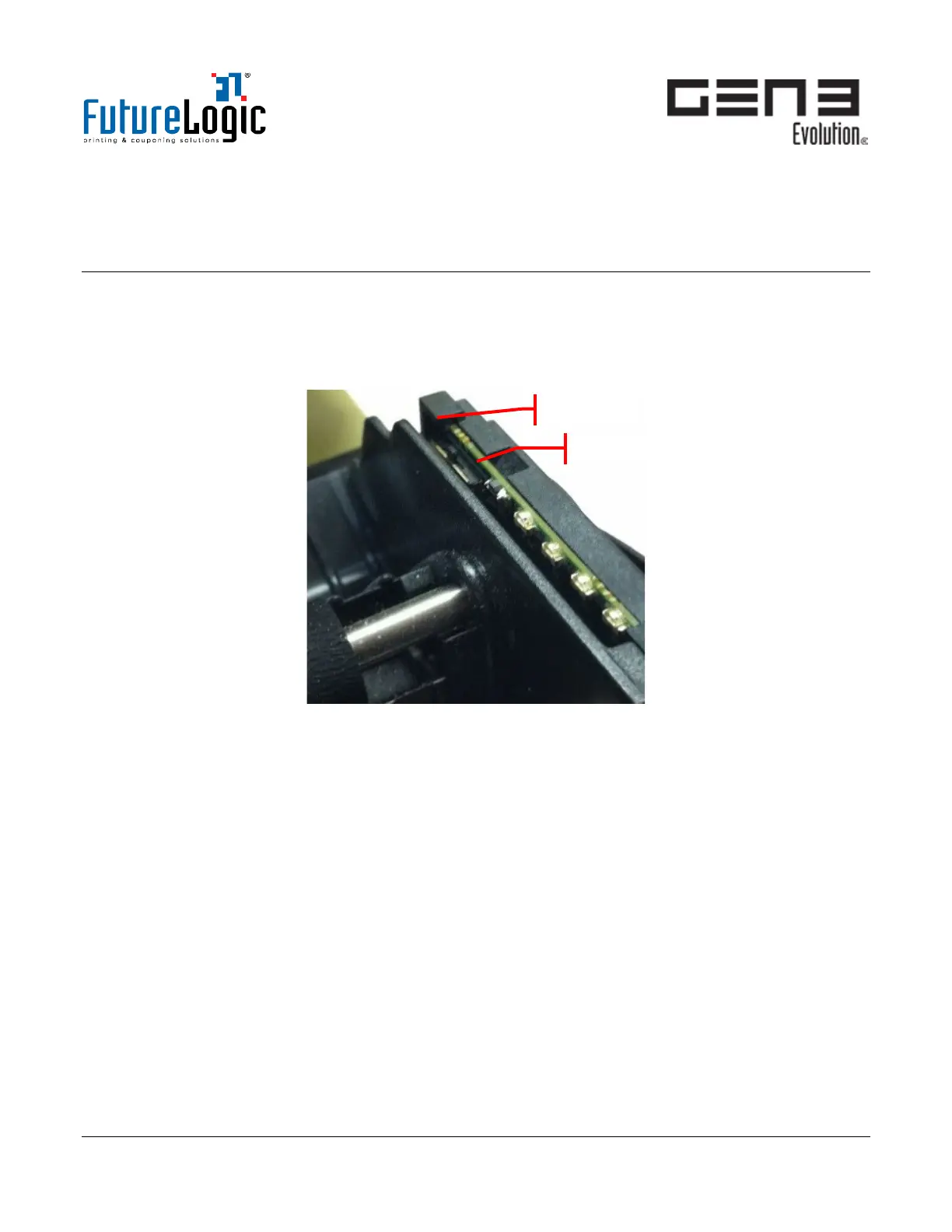
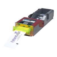
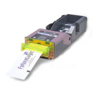
Figure 7-1 Memory/LED Module
The Memory/LED Module includes a Communication Setting Switch (COMM Switch) next to the LED
indicators as shown. The COMM switch is a momentary three-position slide switch where the middle is the
normal position.
• To activate Position 1: slide the switch towards the Ticket Tray.
• To activate Position 2: slide the switch towards the front of the printer.
When using the COMM switch, note the following:
• The de-bounce time for either activating or deactivating each switch position is 50 ms.
• The selection of either Position 1 settings (0 to 7) or Position 2 settings (0 to 15) operates in a ring
cycle. It will re-start from zero after the maximum is reached.
• Position 1 and Position 2 have an auto-increment function that advances the appropriate index by
holding the switch in the active position for more than three quarters of a second.