Operators and Technicians Manual
2011 – 2014 FutureLogic, Incorporated. All Rights Reserved. MNL Page iii 04/10/2014
MNL-000067 REV.X03
List of Figures
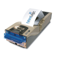
Figure 3-1 GEN3 Evolution Printer Components ................................................................................ 3
Figure 3-2 Ticket and Print Head Release Levers ............................................................................... 4
Figure 3-3 Pull Printer Forward ........................................................................................................... 4
Figure 3-4 Fan Paper ............................................................................................................................ 5
Figure 3-5 Load Ticket Stack ................................................................................................................ 5
Figure 3-6 Lid Release Lever and Ticket In Slot .................................................................................. 6
Figure 3-7 Print Head Release Lever ................................................................................................... 6
Figure 4-1 Printer Sensors .................................................................................................................... 7
Figure 4-2 Pull Printer Forward ........................................................................................................... 8
Figure 4-3 Disconnect Interface Cable Connector ............................................................................. 8
Figure 4-4 Pull and Hold Release Slide ............................................................................................... 8
Figure 4-5 Printer Cleaning Kit ............................................................................................................ 9
Figure 4-6 Pull Print Head Release Lever ............................................................................................ 9
Figure 4-7 Clean Print Head .............................................................................................................. 10
Figure 4-8 Clean Sensors .................................................................................................................... 10
Figure 4-9 Clean Rollers ..................................................................................................................... 10
Figure 5-1 Firmware Upload Port ...................................................................................................... 11
Figure 5-2 Front Bezel Port ................................................................................................................ 11
Figure 5-3 USB/RS232 Interface Cable ............................................................................................... 12
Figure 5-4 RS232 Evaluation Cable ................................................................................................... 13
Figure 5-5 GDS Adapter Cable .......................................................................................................... 14
Figure 6-1 Configuration Tickets ....................................................................................................... 15
Figure 7-1 Memory/LED Module ....................................................................................................... 17
Figure 7-2 Memory/LED Module Screws ........................................................................................... 19
Figure 7-3 Pull Out Module ............................................................................................................... 19
Figure 8-1 Plug Adapter Cable into Firmware Upload Port ............................................................ 21
Figure 8-2 InstallShield Wizard ......................................................................................................... 23
Figure 8-3 Device Manager ............................................................................................................... 23
Figure 8-4 Update Driver Software Window ................................................................................... 24
Figure 8-5 Device Manager ............................................................................................................... 24
Figure 8-6 Printer Connection to Laptop .......................................................................................... 25
Figure 8-7 FLDFU Main Window ....................................................................................................... 25
Figure 8-8 FLDFU Main Window – Progress Area ............................................................................ 26
Figure 8-9 FLDFU Main Window – Status Area ................................................................................ 26
Figure 9-1 Printer and Laptop Connection ....................................................................................... 28
Figure 9-2 Device Manager – Other Devices .................................................................................... 29
Figure 9-3 Device Manager ............................................................................................................... 29
Figure 9-4 RS232 Evaluation Cable Connections .............................................................................. 30
Figure 9-5 CommWrangler Main Window ....................................................................................... 31
Figure 9-6 Printer Status Window ..................................................................................................... 31
Figure 9-7 CommWrangler – Print Test Tickets ................................................................................ 32