DMC-21x3 Accessories Chapter 5 SDM-20240/20242• 31
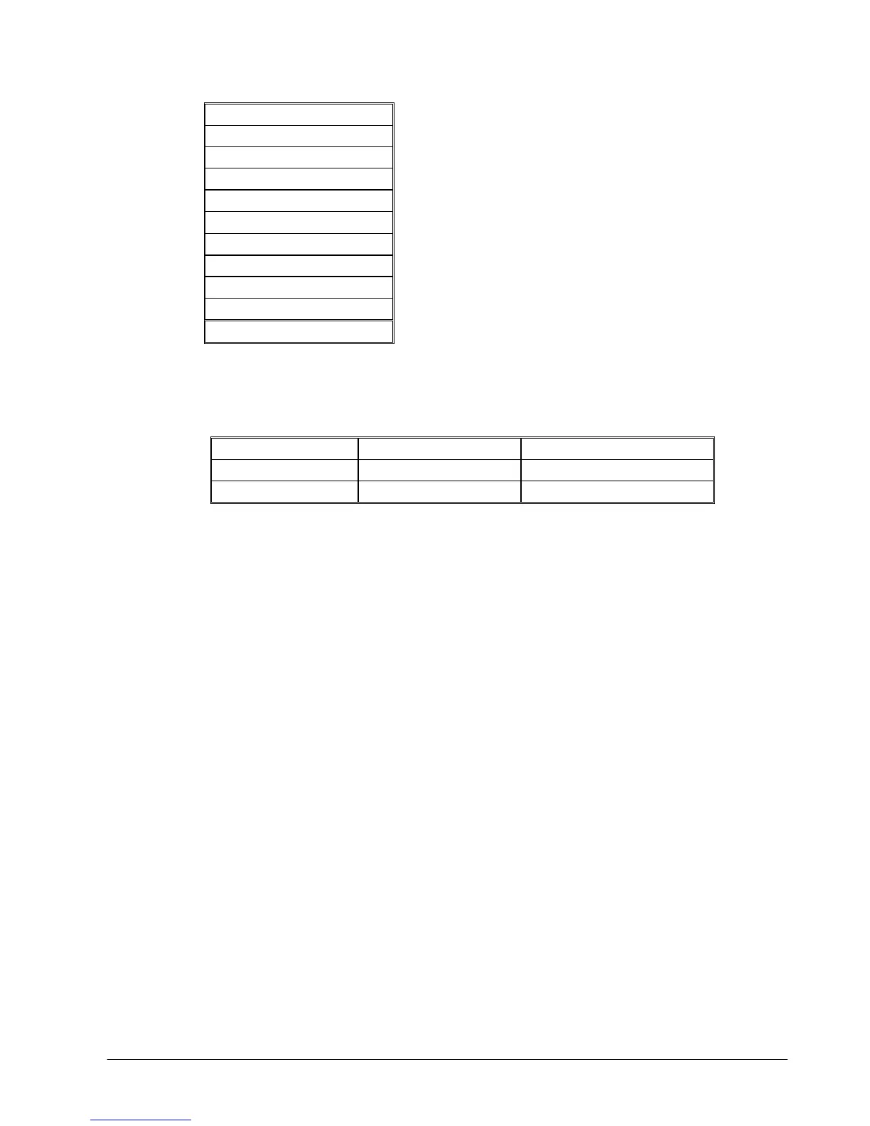
JP8 – Servo Motor Signals
1 XAEN (X Amp Enable)
2 XMCM (X Motor CMD)
3 YAEN (Y Amp Enable)
4 YMCM (Y Motor CMD)
5 ZAEN (Z Amp Enable)
6 ZMCM (Z Motor CMD)
7 WAEN (W Amp Enable)
8 WMCM (W Motor CMD)
9 GND
10 GND
Mating Connectors
Connector Terminal Pins
J1: Power
Molex: 26-03-4041 Molex: 08-50-0189
J2-J5: Motor Leads
Molex: 22-01-3047 Molex: 08-50-0114
______________________________________________________________________________
Configurations for SDM-20240 & SDM-20242
The SDM-20240 & 20242 have jumpers for setting different functions on the amplifier. The
output current per phase can be set as noted in the table below to 0.5, 0.75, 1.0, or 1.4
Amps/phase. Jumpers are also used to control the current level when the motor is holding position
and the degree of microstepping. The SDM-20242 has additional jumpers for extra functionality
The following paragraphs give the details of the jumper settings.
Motor Current Setting
Set the Current Reference jumpers for each axis to determine the maximum (peak) output current
for each motor. The axes X,Y,Z, and W apply to jumpers JP3, JP4, JP5, and JP6 (SDM-20240)
or JPX1, JPY1, JPZ1, and JPW1(SDM-20242) respectively. Four options are available for each
axis: 0.5A, 0.75A, 1.0A, and 1.4 A. In figure below, the X-axis is configured for 0.5A, the Y axis
as 0.75A, the Z-axis with 1.0 A, and the W axis for 1.4 A. (Note: when using the 1.4 A setting, a
cooling fan or adequate air flow may be required.)

 Loading...
