48 • Chapter 8 ICM-20500 DMC-21x3 Accessories
Configuration
The schematic above shows the digital input configuration. For digital inputs 1 to 8, INCOM
connects to the positive (+) terminal of an external DC supply for a sourcing configuration. For
a sinking configuration, the negative (-) supply terminal is connected instead. The same
approach is applied to the Home and Limit switch inputs with LSCOM.
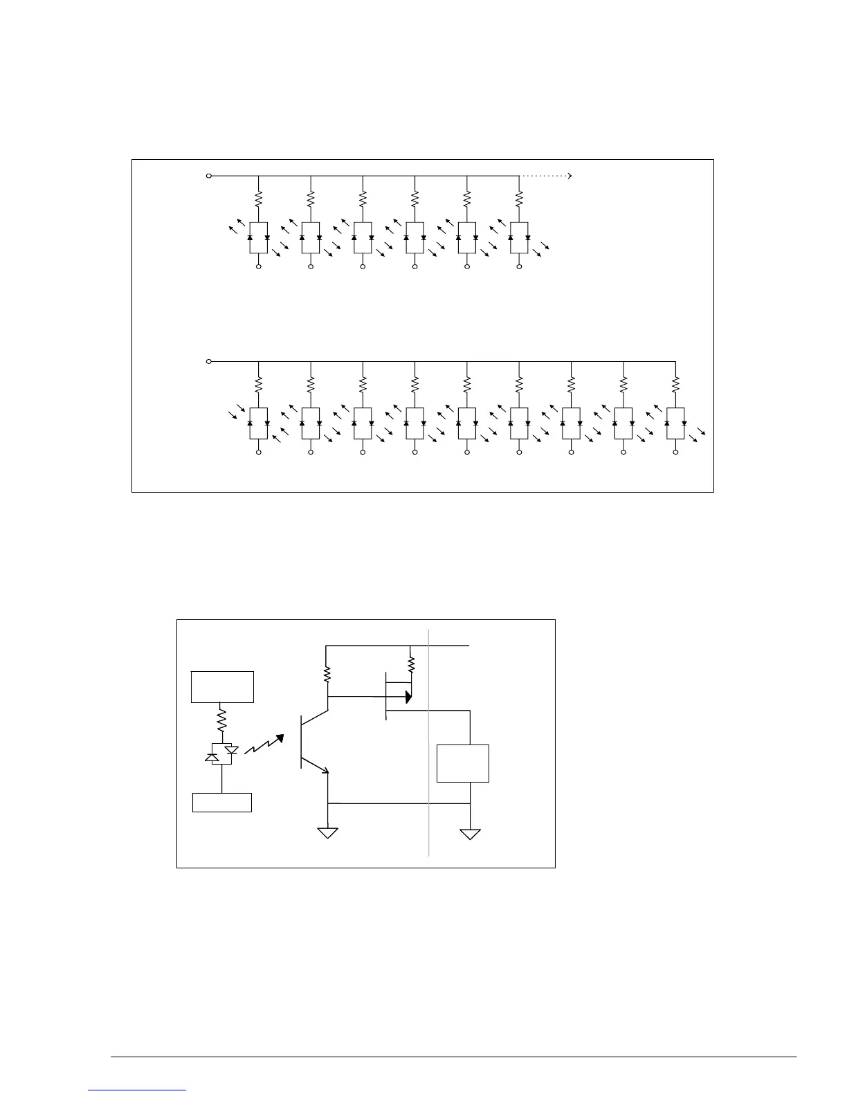
On the digital outputs, the first
four outputs (Outputs 1 to 4)
are high power outputs capable
of providing up to 500 mA at
up to 24 VDC. An external
DC supply must be connected
between Output Supply and
Output Return. The other four
outputs (Outputs 5 to 8) are
opto-isolated and can deliver
up to 25 mA at up to 24 VDC.
The diagram refers only to
outputs 1 to 4. On outputs 5 to
8, there is no FET on final
stage of the output, only the
opto-isolator.
The polarity of outputs 1-4
may be reversed by flipping RP11 180 degrees. The polarity of outputs 5-8 may be reversed by
flipping RP12 180 degrees.
IN1 IN2 IN3 IN4 IN5 IN6 IN7 IN8 ABORT
FLSX RLSX HOMEX FLSY RLSY HOMEY
Additional Limit
Switches(Dependent on
Number of Axes)
(XLATCH) (YLATCH) (ZLATCH) (WLATCH)
Limit
Switch
Common
Input
Common
Voltage
Figure 23 ICM-20500 Digital Inputs
LSCOM
INCOM
RPOUT
5V or GND
SB n = 5V
Load
RP Out
10K
OUTSUP (+)
OUTRET ( -)
MachineICM-20500
RPOUT
5V or GND
SB n = 5V
Load
RP Out
10K
OUTSUP (+)
OUTRET ( -)
MachineICM-20
Figure 24 High Power Outputs

 Loading...
