DMC-21x3 Accessories Chapter 4 ICM-20105• 23
Configurations for ICM-20105
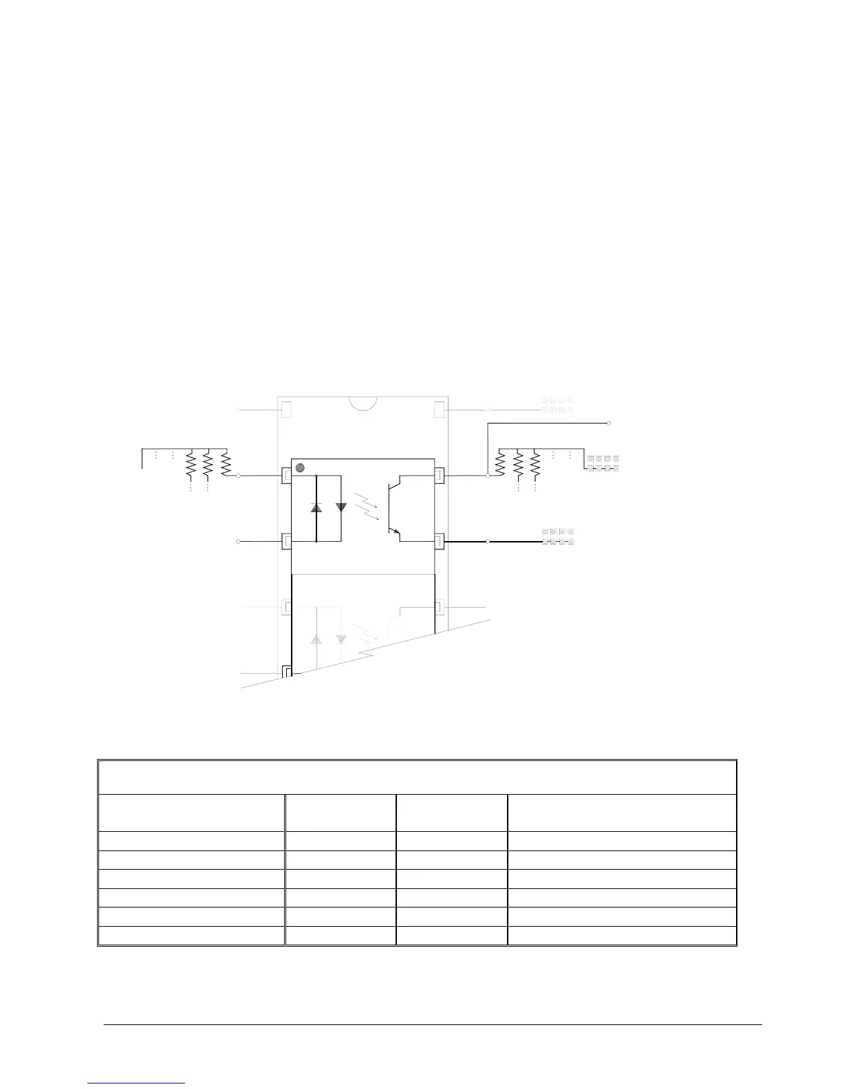
Amplifier Enable Circuit
The ICM-20105 gives the user a broad range of options with regards to the voltage levels present on the enable
signal. The user can choose between High-Amp-Enable (HAEN), Low-Amp-Enable (LAEN), 5V logic, 12V logic,
external voltage supplies up to 24V, sinking, or sourcing. The tables below illustrate the settings for jumpers,
RPacks, and the socketed optocoupler IC. Refer to Figure 7 for precise physical locations of all components. Note
that the resistor pack located at RPAE1 may be reversed to change the active state of the amplifier enable output.
The polarity of RPAE2 must not be changed; however, a different resistor value may be needed to limit the current
to 6 mA . The default value for RPAE2 is 820 ohms, which works at 5V. When using 24 V, RPAE2 should be
replaced with a 4.7 kΩ resistor pack.
Amplifier Enable Circuit
Sinking Output Configuration
(Pin 1 of PS2505 in Pin 2 of Socket U1)
TTL level Amp
Enable signal
from controller
(SH = 5V, MO = 0V)
TTL level Amp
Enable signal
from controller
(SH = 5V, MO = 0V)
5V or GND
P
I
N
1
RPAE1 (470 Ohm)
Pin 1
Pin 1
of socket
Socket U1
RPAE2 (820 Ohm)
+
5
V
G
N
D
A
E
C
O
M
2
+
1
2
V
+
5
V
G
N
D
A
E
C
O
M
2
+
1
2
V
AEC2
JP2
Amp Enable Output to Drive
AEC2
+
1
2
V
A
E
C
O
M
1
+
5
V
G
N
D
JP2
AEC1
JP1
Figure 8 Amplifier Enable Circuit Output Configuration
Sinking Configuration (pin1 of opto chip in pin2 of socket U1)
Logic State JP1 JP2
RPAE1
(square pin next to RPAE1 label is 5V)
5V, HAEN (Default Configuration) 5V - AEC1 GND - AEC2 Dot on R-pack next to RPAE1 label
5V, LAEN 5V - AEC1 GND - AEC2 Dot on R-pack opposite RPAE1 label
12V, HAEN +12V - AEC1 GND - AEC2 Dot on R-pack next to RPAE1 label
12V, LAEN +12V - AEC1 GND - AEC2 Dot on R-pack opposite RPAE1 label
Isolated 24V, HAEN AECOM1 - AEC1 AECOM2 - AEC2 Dot on R-pack next to RPAE1 label
Isolated 24V, LAEN AECOM1 - AEC1 AECOM2 - AEC2 Dot on R-pack opposite RPAE1 label
 Loading...

