Instructions for SL500DC/SL800DC
www.gatexpertstore.com
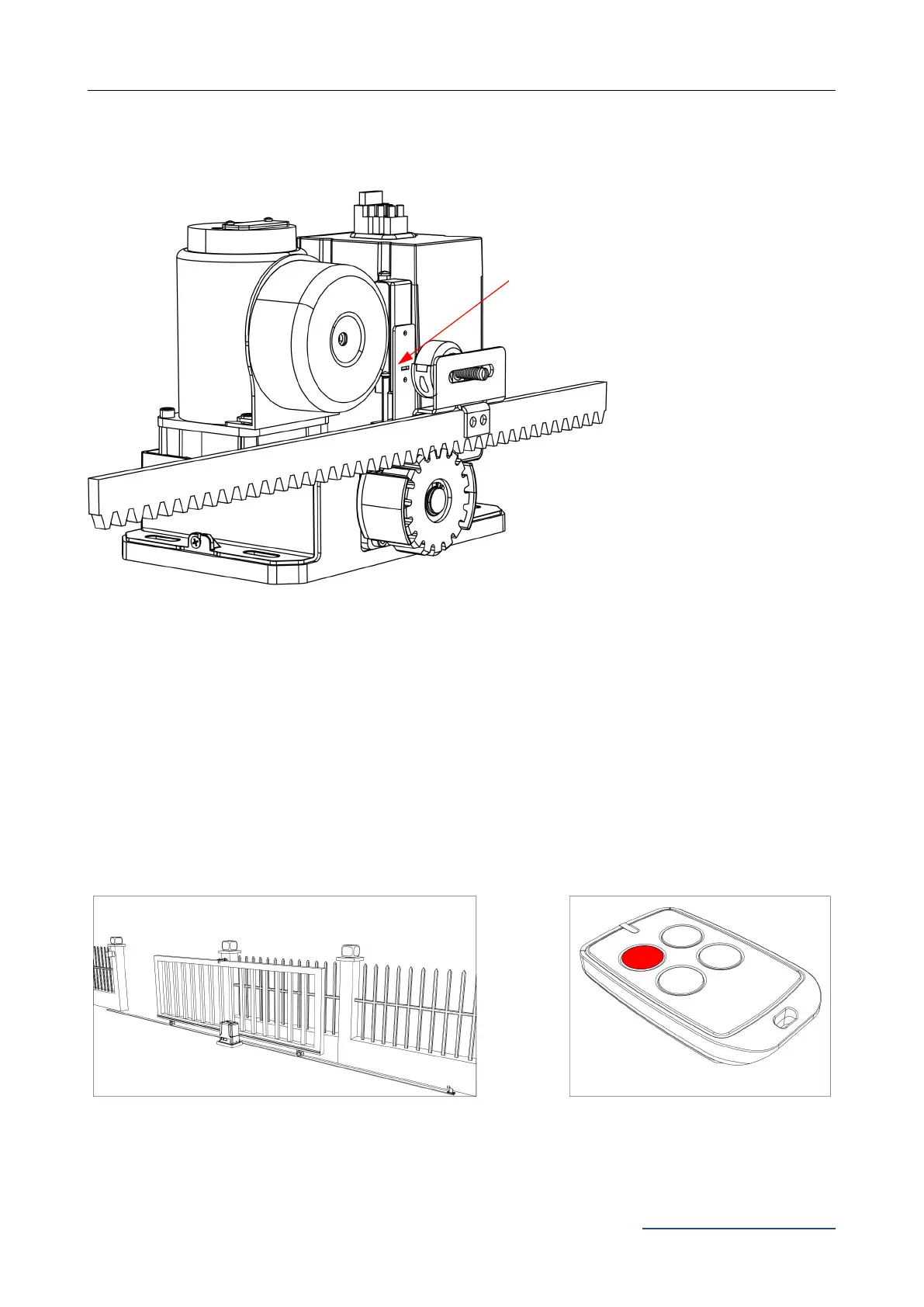
Drawing of recommended installation height for the limit switch stop bracket:
Figure 17
Step 8 - Powering on
· Ensure that the outer cover has been fitted and fastened back onto the motor base.
· Before powering up the gate opener make sure the gate can travel by hand in manual mode
(key unlocked).
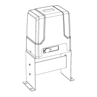
· Slide the gate to between the middle of the posts, approximately (see below diagrams).
· Lock the manual release spanner (key locked) in readiness for automatic mode.
· Plug the power cord into an approved RCD protected weatherproof outlet.
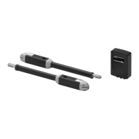
· Remote controls included in this kit are factory paired ready for use.
Figure 18
1. The installation height of the magnet limit
switch stop must be parallel to the slot on
the magnetic limit switch and be central.
Cannot be offset up and down too much,
or it will affect the detection.
2. The gap between the magnet limit switch
stop and magnetic limit switch should be
less than 3cm.