CHAPTER 6: SETPOINTS S5 INPUTS/OUTPUTS
339 MOTOR PROTECTION SYSTEM – INSTRUCTION MANUAL 6–153
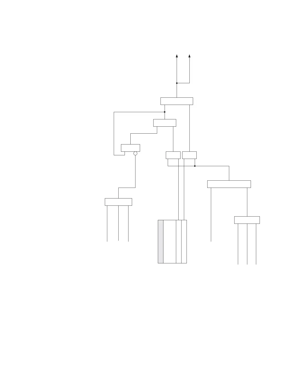
Figure 6-66: Auxiliary relays
Critical Failure Relay #7 - Input/Output “E”
The 339 relay is also equipped with one output relay (# 7 - “Critical Failure Relay”) for fail-
safe indication. There are no user-programmable setpoints associated with this output
relay. The logic for this relay is shown below.
The Critical Failure Relay (Output Relay 7) is a form C contact (refer to the Typical Wiring
Diagram) with one Normally Open, and one Normally Closed contact (no control power).
Output Relay 7 is energized or de-energized (state change) depending on the following
conditions:
1. Output Relay 7 will be de-energized, if the relay is not in IN-SERVICE mode or the
control power is not applied to the relay
From Protection Feature
OR
From Control Feature
From Maintenance Feature
Assigned Aux Outputs:
AND
Relay Status
(Ready = 1)
SETPOINT
RELAY (4 to 6) AUXILIARY
OUTPUT TYPE
Latched
Self-Reset
AND
AND
OR
AND
OR
RESET (Relay Keypad)
RESET (Communications)
RESET (Input)
S4 Control
OR
Operate Aux
Output Relay (4 to 6)
Message & Event Recorder
896777.cdr