6–154 339 MOTOR PROTECTION SYSTEM – INSTRUCTION MANUAL
S5 INPUTS/OUTPUTS CHAPTER 6: SETPOINTS
2. Output Relay 7 will be energized when the control power is applied to the relay and
the relay is in IN-SERVICE mode.
3. Output Relay 7 will stay de-energized, when the control power is applied, if the relay
was not programmed as “Ready”, or upon major self-test failure during relay boot-up.
4. Output Relay 7 will change state from energized to de-energized if the 339 relay
experiences any major self-test failure.
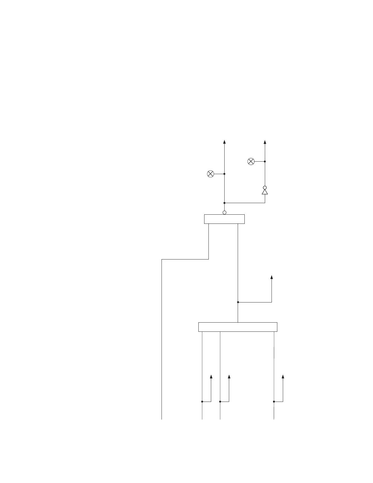
Figure 6-67: Output relay 7: Critical Failure Relay
ANY MAJOR ERROR
(Forces the Relay into “Not Ready” state)
OR
S1 SETPOINTS / S1 RELAY SETUP / S1 INSTALLATION / RELAY STATUS
(Not Ready = 1)
LED: IN SERVICE
OR
.
.
.
.
.
.
Message & Ev
ent Recorder
Major Error 1
See all major errors listed in the
table below
To Output Relays 1 to 6
In Service
De-energize Output Relay #7
(Critical Failure Relay)
LED: TROUBLE
898778.CDR
Major Error 2
Message & Event Recorder
Major Error XX
Message & Event Recorder
ANY MAJOR ERROR
Message & Event Recorder