CHAPTER 6: SETPOINTS S5 INPUTS/OUTPUTS
339 MOTOR PROTECTION SYSTEM – INSTRUCTION MANUAL 6–163
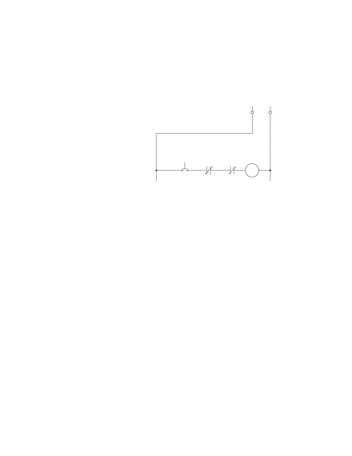
Output Relay 3 Start Inhibit - Input/Output “R”
There are no user-programmable setpoints associated with the START INHIBIT relay. If
there is a lockout time, the START INHIBIT relay prevents or inhibits the start of the motor
based on the MOTOR LOCKOUT TIME. The operation of this output relay is always self-
reset, so it will automatically reset when all lockout timers expire. This relay should be
wired in series with the start pushbutton to prevent motor starting.
Figure 6-74: Breaker: Wiring for Start Inhibit
Critical Failure Relay 4 - Input/Output “R”
The 339 relay is also equipped with one output relay (#4 - “Critical Failure Relay”) for fail-
safe indication. There are no user-programmable setpoints associated with this output
relay. The logic for this relay is shown below.
The Critical Failure Relay (Output Relay 4) is a form C contact (refer to the Typical Wiring
Diagram) with one Normally Open, and one Normally Closed contact (no control power).
Output Relay 4 is energized or de-energized (state change) depending on the following
conditions:
1. Output Relay 4 will be de-energized, if the relay is not in IN-SERVICE mode or the
control power is not applied to the relay
2. Output Relay 4 will be energized when the control power is applied to the relay and
the relay is in IN-SERVICE mode.
3. Output Relay 4 will stay de-energized, when the control power is applied, if the relay
was not programmed as “Ready”, or upon major self-test failure during relay boot-up.
4. Output Relay 4 will change state from energized to de-energized if the 339 relay
experiences any major self-test failure.
Control Power
Start
Start Inhibit
Output Relay 3
52b
Close
Coil
896841.cdr