CHAPTER 4: INTERFACES FRONT PANEL INTERFACE
C70 CAPACITOR BANK PROTECTION AND CONTROL SYSTEM – INSTRUCTION MANUAL 4-15
4
4.2 Front panel interface
This section explains use of the enhanced, standard, and graphical front panels.
4.2.1 Front panel
4.2.1.1 Enhanced front panel
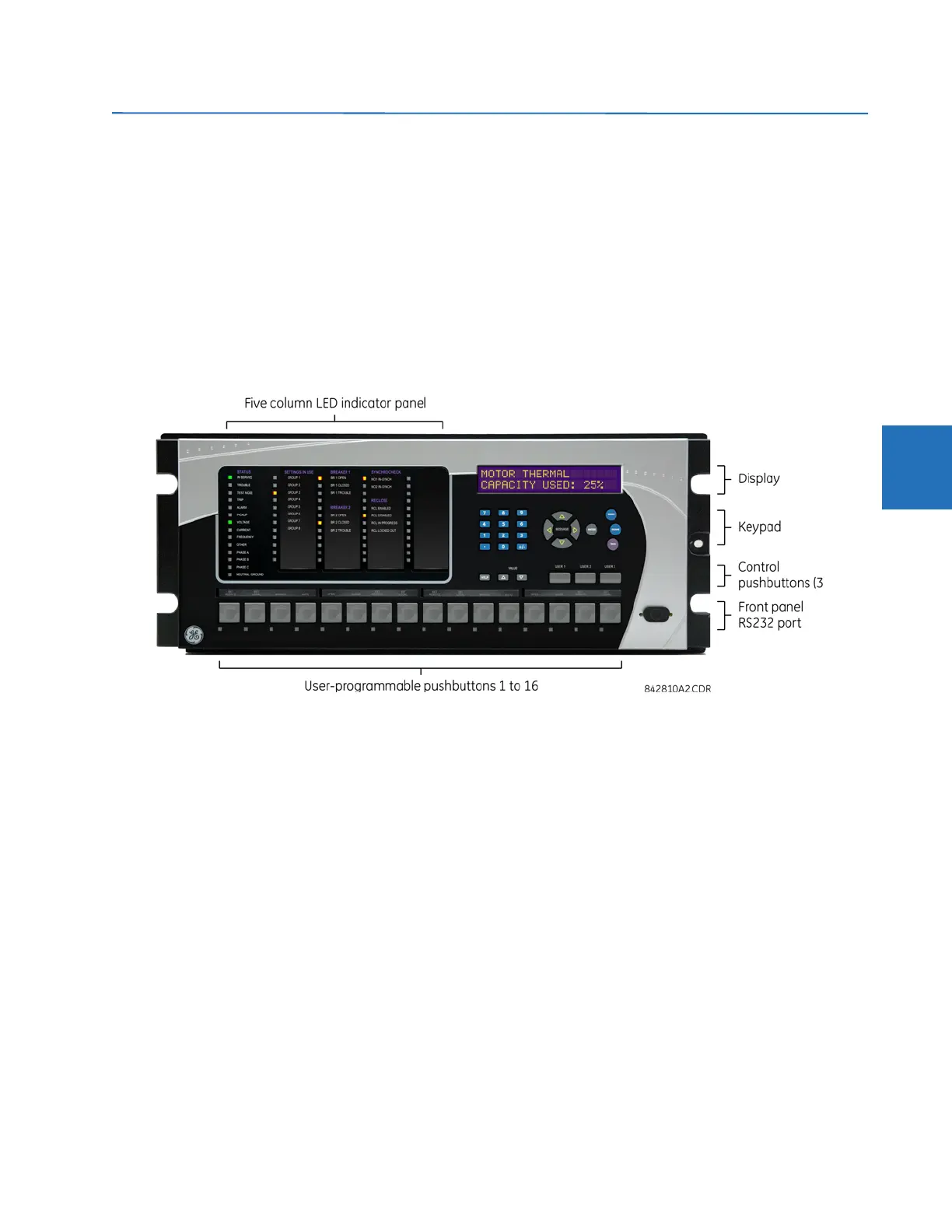
The enhanced front panel consists of LED panels, an RS232 port, keypad, LCD display, control pushbuttons, and optional
user-programmable pushbuttons.
The front panel is hinged to allow access to removable modules inside the chassis. The C70 enhanced front panel can be
horizontal or vertical. The following figure shows the horizontal front panel.
Figure 4-17: Enhanced horizontal front panel
4.2.1.2 Standard front panel
The standard front panel consists of LED panels, an RS232 port, keypad, LCD display, control pushbuttons, and optional
user-programmable pushbuttons.
The front panel is hinged to allow easy access to removable modules inside the chassis. There is also a removable dust
cover that is to be removed when accessing the keypad. The C70 standard front panel can be horizontal or vertical. The
following figure shows the horizontal front panel.