8-18 C70 CAPACITOR BANK PROTECTION AND CONTROL SYSTEM – INSTRUCTION MANUAL
SETTINGS EXAMPLE CHAPTER 8: APPLICATION OF SETTINGS
8
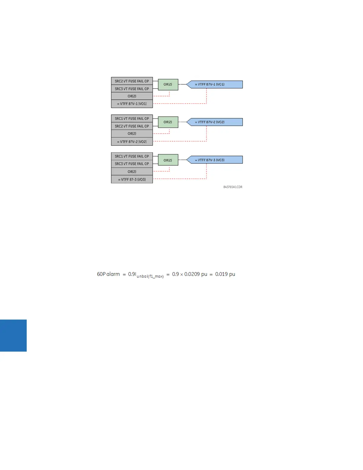
The voltage differential element must be blocked during a VT fuse failure at any tap. The voltage differential element is
dependent on both source VTs. These VTs must be blocked if one or both of them has a VT fuse failure condition. Therefore,
as shown in the following figure, a blocking input for each element is created with FlexLogic.
Figure 8-13: Voltage differential blocking during VT fuse failure
The 87V-2 and 87V-3 differential elements for the strings against tap voltage are created in a similar manner. In these
cases, the K factor is different, reflecting the voltage division of K = 463.8194 between the string and tap capacitor
voltages.
8.4.6 Bank phase current unbalance settings
Two phase current unbalance (ANSI 60P) stages are used to provide trip and alarm levels during capacitor unit failures in
each differential element.
The pickup setting for the stage 1 phase current unbalance alarm element is programmed for one element failure.
Eq. 8-25
Therefore, the alarm delay is specified as 10 seconds. The following setting values are programmed in the EnerVista UR
Setup software.