CHAPTER 5: SETTINGS PRODUCT SETUP
C70 CAPACITOR BANK PROTECTION AND CONTROL SYSTEM – INSTRUCTION MANUAL 5-115
5
5.3.9.3 Analog channels
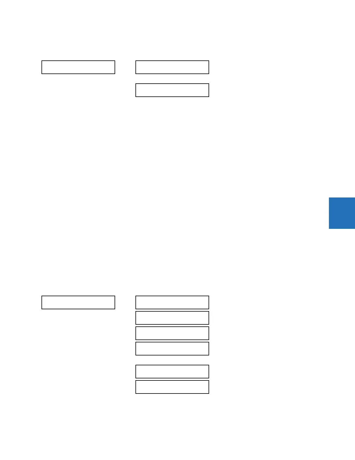
SETTINGS PRODUCT SETUP OSCILLOGRAPHY ANALOG CHANNELS
These settings select the metering actual value recorded in an oscillography trace. The length of each oscillography trace
depends in part on the number of parameters selected here. Parameters set to “Off” are ignored. The parameters available
in a given relay depend on
•the type of relay,
• the type and number of CT/VT hardware modules installed, and
• the type and number of analog input hardware modules installed
A list of all possible analog metering actual value parameters is presented in Appendix A: FlexAnalog Parameters. The
parameter index number shown in any of the tables is used to expedite the selection of the parameter on the relay display.
It can be time-consuming to scan through the list of parameters via the relay keypad and display — entering this number
via the relay keypad causes the corresponding parameter to display.
All eight CT/VT module channels are stored in the oscillography file. The CT/VT module channels are named as follows:
<slot_letter><terminal_number>—<I or V><phase A, B, or C, or 4th input>
The fourth current input in a bank is called IG, and the fourth voltage input in a bank is called VX. For example, F2-IB
designates the IB signal on terminal 2 of the CT/VT module in slot F.
If there are no CT/VT modules and analog input modules, no analog traces appear in the file; only the digital traces appear.
The source harmonic indices appear as oscillography analog channels numbered from 0 to 23. These correspond directly
to the to the 2nd to 25th harmonics in the relay as follows:
Analog channel 0 ↔ 2nd harmonic
Analog channel 1 ↔ 3rd harmonic
...
Analog channel 23 ↔ 25th harmonic
5.3.10 Data logger
SETTINGS PRODUCT SETUP DATA LOGGER
ANALOG CHANNELS
ANALOG CHANNEL 1:
Off
Range: Off, any FlexAnalog/actual value parameter
See Appendix A for list
ANALOG CHANNEL 16:
Off
Range: Off, any FlexAnalog/actual value parameter
See Appendix A for list
DATA LOGGER
DATA LOGGER MODE:
Continuous
Range: Continuous, Trigger
DATA LOGGER TRIGGER:
Off
Range: FlexLogic operand
DATA LOGGER RATE:
60000 msec
Range: 15 to 3600000 ms in steps of 1
DATA LOGGER CHNL 1:
Off
Range: Off, any FlexAnalog/actual value parameter
See Appendix A for list
DATA LOGGER CHNL 16:
Off
Range: Off, any FlexAnalog/actual value parameter
See Appendix A for list
DATA LOGGER CONFIG:
0 CHNL x 0.0 DAYS
Range: Not applicable - shows computed data only