5-144 C70 CAPACITOR BANK PROTECTION AND CONTROL SYSTEM – INSTRUCTION MANUAL
SYSTEM SETUP CHAPTER 5: SETTINGS
5
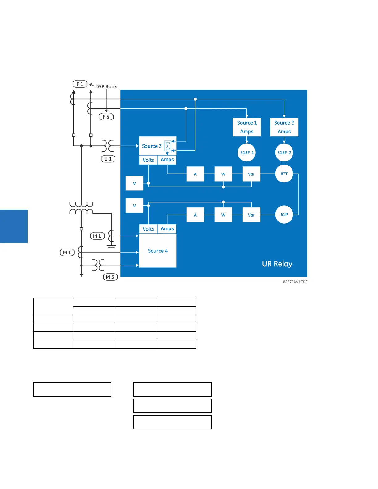
This configuration can be used on a two-winding transformer, with one winding connected into a breaker-and-a-half
system. The following figure shows the arrangement of sources used to provide the functions required in this application,
and the CT/VT inputs that are used to provide the data.
Figure 5-67: Example of use of sources
5.5.4 Breakers
SETTINGS SYSTEM SETUP BREAKERS BREAKER 1(3)
Y LV D HV AUX
SRC 1 SRC 2 SRC 3
Phase CT M1 F1+F5 None
Ground CT M1 None None
Phase VT M5 None None
Aux VT None None U1
BREAKER 1
BREAKER 1
FUNCTION: Disabled
Range: Disabled, Enabled
BREAKER1 PUSH BUTTON
CONTROL: Disabled
Range: Disabled, Enabled
BREAKER 1 TAGGING:
Disabled
Range: Disabled, Enabled