CHAPTER 4: INTERFACES FLEXLOGIC DESIGN USING ENGINEER
C70 CAPACITOR BANK PROTECTION AND CONTROL SYSTEM – INSTRUCTION MANUAL 4-63
4
• Toolbars
4.4.1 Design logic
FlexLogic can be created with a block diagram. Note that although work is completed in the Offline Window area of the
software, communication occurs with the online device, for example when switching to monitoring mode.
The following procedures are outlined:
•Examples
• Add existing FlexLogic equations
• Create a logic diagram/sheet
• Rapidly add logic blocks in sequence
• Connect two logic diagrams/sheets
• Optimize the logic
• Change logic order
•Search logic
• Exclude sheet from compile
4.4.1.1 Examples
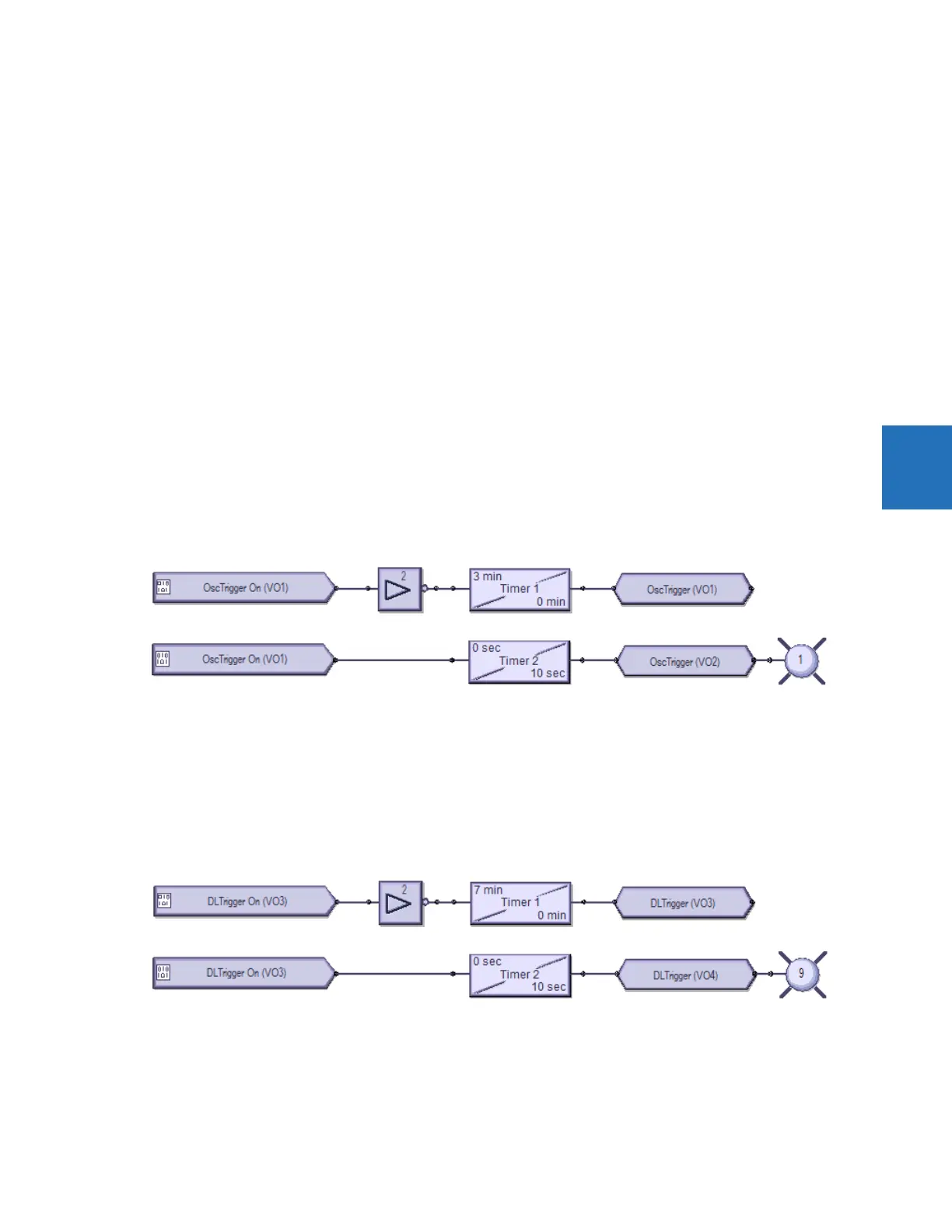
Create oscillography trigger every three minutes
Figure 4-66: Three-minute timer turns on LED for 10 seconds
Preparation — Under Settings > Inputs/Outputs > Virtual Outputs, the first and second virtual outputs are named
OscTrigger
Top logic — Three-minute timer trigger
Bottom logic — Turn on LED 1 for 10 seconds when the trigger starts
Create data logger trigger every seven minutes
Figure 4-67: Seven-minute timer turns on LED for 10 seconds
Preparation — Under Settings > Inputs/Outputs > Virtual Outputs, virtual outputs 3 and 4 are named DLTrigger
Top logic — Seven-minute timer trigger
Bottom logic — Turn on LED 9 for 10 seconds when the trigger starts