8-14 C70 CAPACITOR BANK PROTECTION AND CONTROL SYSTEM – INSTRUCTION MANUAL
SETTINGS EXAMPLE CHAPTER 8: APPLICATION OF SETTINGS
8
8.4.3 Source assignment
The following sources must be assigned for the protection functions indicated:
• Source 1 (bus) is assigned with CT and VT banks connected to the bus, providing a signal source for overcurrent, phase
current unbalance, overvoltage, and undervoltage functions
• Source 2 (tap 1) and source 3 (tap 2) are assigned with the VT banks and split window CT bank connected to the tap
point of two strings of the bank, providing a signal source for the voltage differential and phase unbalance functions
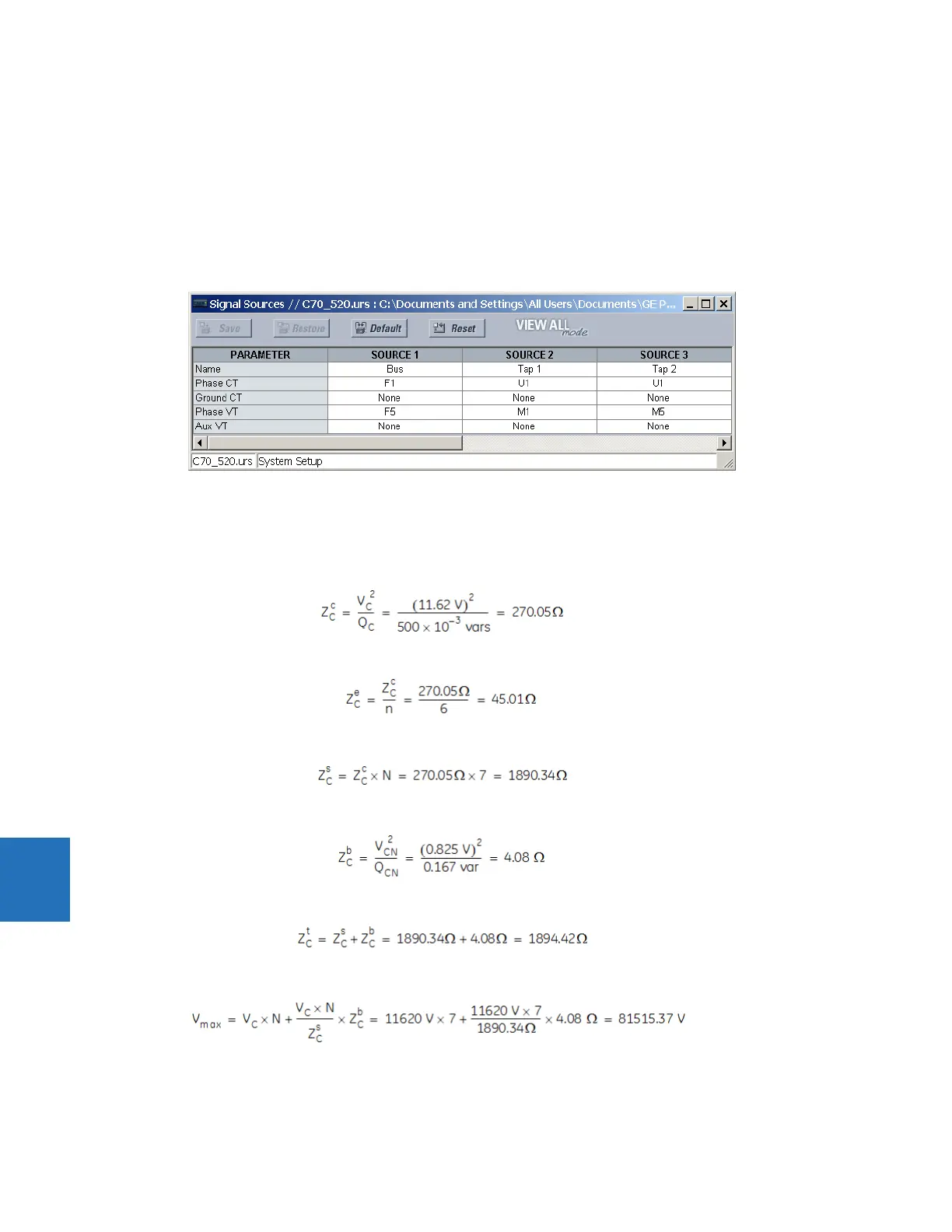
The CT and VT connections shown in the earlier figure are assigned the following values in EnerVista UR Setup.
8.4.4 Bank unbalance calculations
The following values are used in unbalance calculations.
The impedance of one capacitor can:
Eq. 8-5
The impedance of one capacitor element, with n = 6 capacitor elements per can:
Eq. 8-6
The impedance of the top healthy capacitor string:
Eq. 8-7
The impedance of the bottom capacitor can:
Eq. 8-8
The total impedance of the healthy capacitor string:
Eq. 8-9
The maximum rated line-to-neutral system voltage:
Eq. 8-10