CHAPTER 8: APPLICATION OF SETTINGS SETTINGS EXAMPLE
C70 CAPACITOR BANK PROTECTION AND CONTROL SYSTEM – INSTRUCTION MANUAL 8-13
8
The VT channels are connected as follows:
• The type 8L CT/VT module F5 to F7 three-phase VT channels are connected to the bus side three-phase VTs with a
138 / 0.115 kV ratio
• The type 8V CT/VT module M1 to M3 and M5 to M7 three-phase VT channels are connected to two tap VTs with a
1.25 / 0.25 kV ratio. The nominal voltage is calculated below for normal bank conditions and a nominal system voltage
of 138 kV (see impedance calculations the following sub-section).
The nominal bus phase VT voltage is:
Eq. 8-1
The nominal tap VT voltage is:
Eq. 8-2
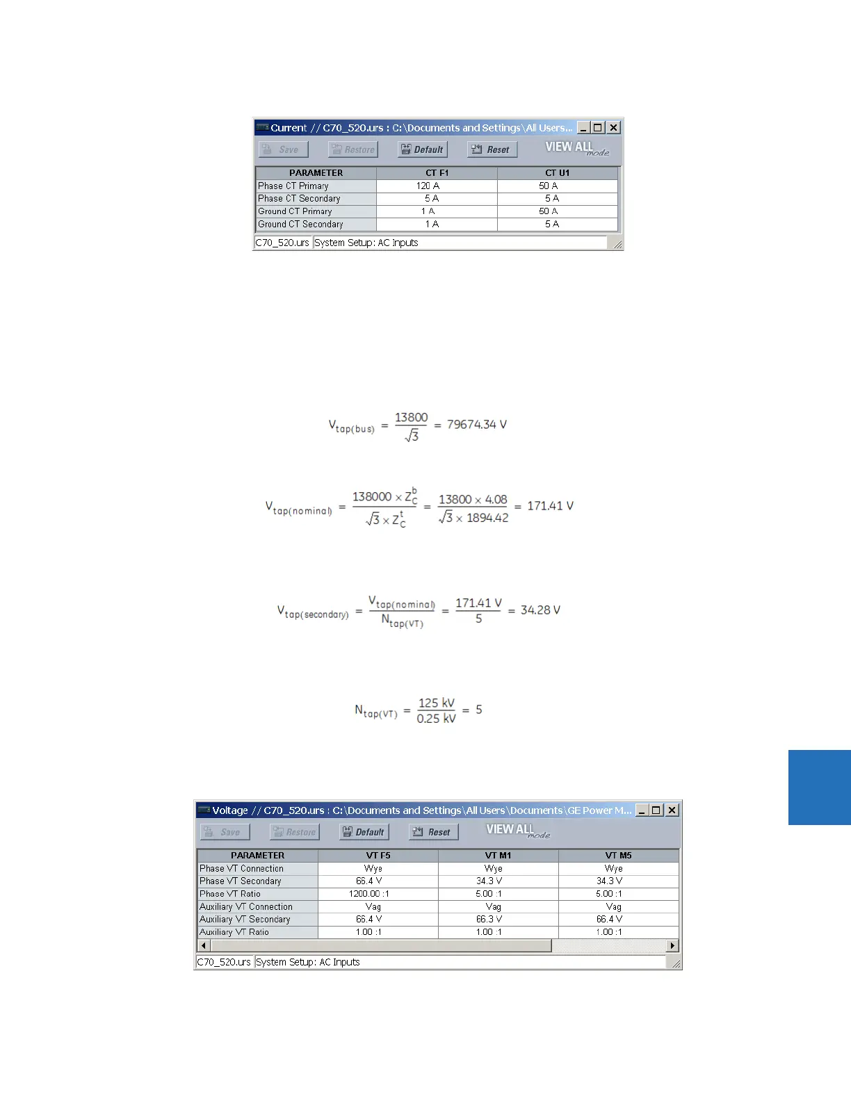
Therefore, the tap VT secondary voltage is set as:
Eq. 8-3
Where the VT ratio N
tap(VT)
is calculated as:
Eq. 8-4
The following settings are applied in the EnerVista UR Setup software.