5-224 C70 CAPACITOR BANK PROTECTION AND CONTROL SYSTEM – INSTRUCTION MANUAL
GROUPED ELEMENTS CHAPTER 5: SETTINGS
5
NEG SEQ DIR OC1 TYPE — Selects the operating mode for the overcurrent unit of the element. The choices are “Neg
Sequence” and “Zero Sequence.” In some applications it is advantageous to use a directional negative-sequence
overcurrent function instead of a directional zero-sequence overcurrent function as inter-circuit mutual effects are
minimized.
NEG SEQ DIR OC1 POS-SEQ RESTRAINT — Controls the positive-sequence restraint. Set it to 0.063 (in “Zero Sequence” mode)
or 0.125 (in “Neg Sequence” mode) for backward compatibility with revisions 3.40 and earlier. Set it to zero to remove the
restraint. Set it higher if large system unbalances or poor CT performance are expected.
NEG SEQ DIR OC1 FWD ECA — Select the element characteristic angle (ECA) for the forward direction. The element
characteristic angle in the reverse direction is the angle set for the forward direction shifted by 180°.
NEG SEQ DIR OC1 FWD LIMIT ANGLE — Defines a symmetrical limit angle (in both directions from the ECA) for the forward
direction.
NEG SEQ DIR OC1 FWD PICKUP — Defines the pickup level for the overcurrent unit in the forward direction. This pickup
threshold applies to zero-sequence or negative-sequence current based on the
NEG SEQ DIR OC1 TYPE setting. When
specifying this setting, keep in mind that the design uses a positive-sequence restraint technique.
NEG SEQ DIR OC1 REV LIMIT ANGLE — Defines a symmetrical limit angle (in both directions from the ECA) for the reverse
direction.
NEG SEQ DIR OC1 REV PICKUP — Defines the pickup level for the overcurrent unit in the reverse direction. This pickup
threshold applies to zero-sequence or negative-sequence current based on the
NEG SEQ DIR OC1 TYPE setting. When
selecting this setting, keep in mind that the design uses a positive-sequence restraint technique.
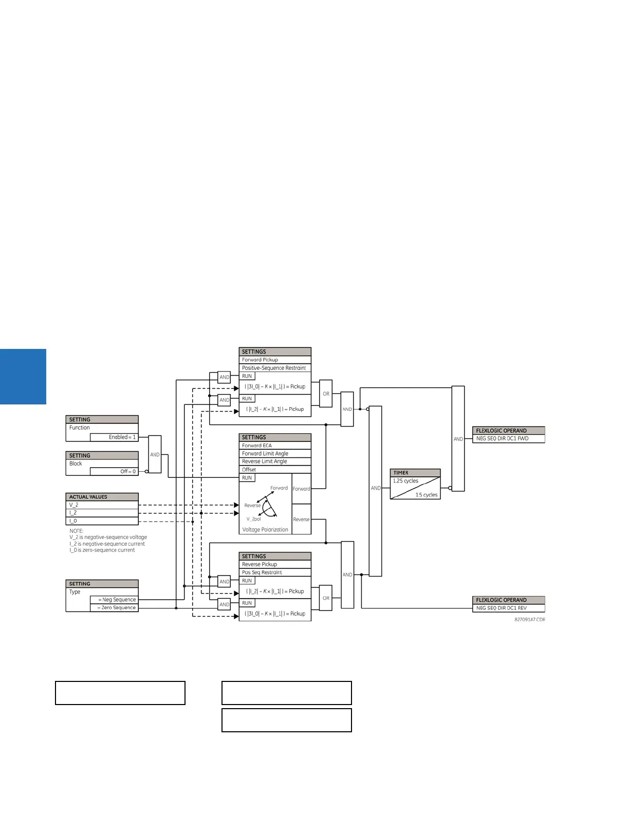
Figure 5-115: Negative-sequence directional OC1 logic
5.7.7 Breaker failure (ANSI 50BF)
SETTINGS GROUPED ELEMENTS SETTING GROUP 1(6) BREAKER FAILURE BREAKER FAILURE 1(3)
BREAKER FAILURE 1
BF1 FUNCTION:
Disabled
Range: Disabled, Enabled
BF1 MODE:
3-Pole
Range: 3-Pole, 1-Pole