4-80 C70 CAPACITOR BANK PROTECTION AND CONTROL SYSTEM – INSTRUCTION MANUAL
FLEXLOGIC DESIGN USING ENGINEER CHAPTER 4: INTERFACES
4
4.4.7 Toolbars
These are toggled in the View > Toolbar menu.
The UR symbols are displayed for the toolbox icons. They change when the default setting is changed to IEC or ISO
symbols. The symbols displayed in the toolbox also vary by firmware version, reflecting what is supported for each release.
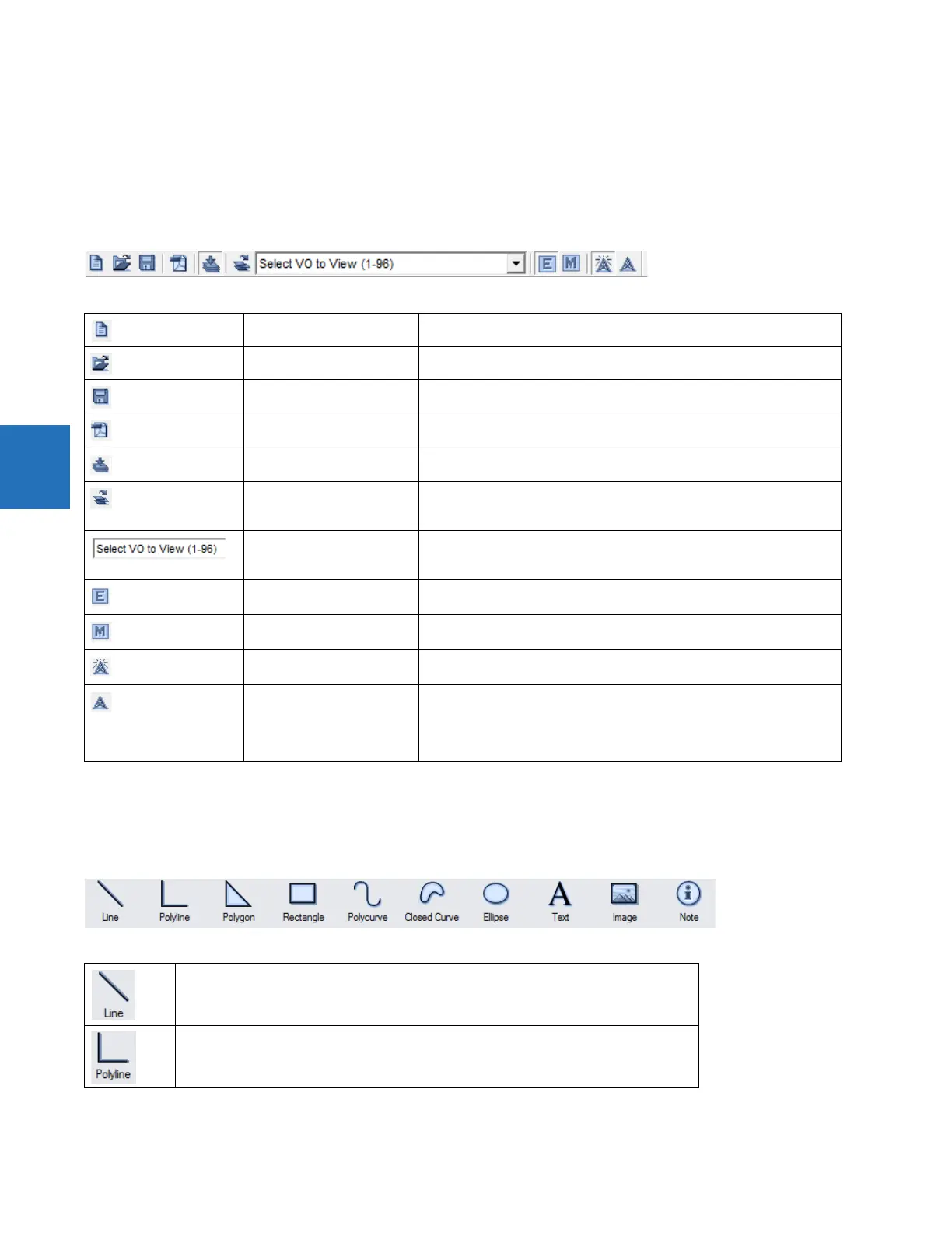
4.4.7.1 FlexLogic Editor toolbar
4.4.7.2 Token Toolbox
Drawing Tools
New Device Create a new settings file
Open File Open an existing settings file in the URS, CID, or IID format
Save FlexLogic Save the Logic Designer diagram
PDF Report Create a PDF document from Logic Designer diagram(s). Settings can be
changed under File > Preferences > Workbook Setup.
Toggle Compile Window Display or hide the compile window area
Sort Order Select to change the sort order of the Virtual Output list to the right of the
icon. Virtual Outputs can be sorted numerically in ascending and
descending order based on numbers and names.
Select VO to View (x - x) Select a Virtual Output to locate and select it in the workbook. Each Virtual
Output listed also contains the name of the sheet where the Virtual Output
is located.
Edit Mode
Logic Designer
Switch to Logic Designer mode
Monitor Mode
Logic Monitor
Switch to Logic Monitor mode
Turn On ALL Communications Turn on all communications to all Logic Designer diagrams that are in the
monitoring mode. Default upon each launch of Engineer.
Turn Off All Communications Turn off all communications to all Logic Designer diagrams that are in the
monitoring mode. This is a legacy function for serial communication to turn
off communication to devices. Turning off communication applies to the
current session only. When you re-launch the EnerVista software,
communication is on by default.
Draw a line. Click and drag to draw.
Draw multiple joined lines. Click and drag for each line. Double-click to finish.