5-150 C70 CAPACITOR BANK PROTECTION AND CONTROL SYSTEM – INSTRUCTION MANUAL
SYSTEM SETUP CHAPTER 5: SETTINGS
5
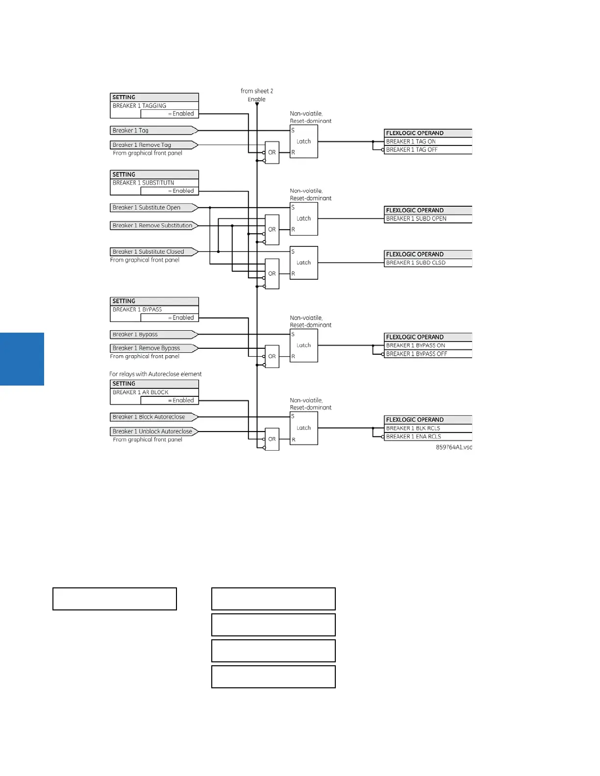
Figure 5-70: Dual breaker / graphical front panel control logic (Sheet 3 of 3)
The breaker element has direct hard-coded connections to the IEC 61850 model as shown in the logic diagram. This allows
remote open/close operation of each breaker, using either CSWI or XCBR IEC 61850 logical nodes. IEC 61850 select-before-
operate functionality, local/remote switch functionality, along with blocking of open/close commands are provided. Note
that the dwell time for the IEC 61850 trip and close commands shown is one protection pass only. To maintain the close/
open command for a certain time, do so by setting the seal-in timers
BREAKER 1 OPEN SEAL-IN and MANUAL CLOSE RECAL1
TIME
, on the contact outputs using the "Seal-in" setting, in the Trip Output element, and/or in FlexLogic.
5.5.5 Disconnect switch control
SETTINGS SYSTEM SETUP SWITCHES SWITCH 1(12)
SWITCH 1
SWITCH 1
FUNCTION: Disabled
Range: Disabled, Enabled
SWITCH 1 NAME:
SW 1
Range: up to six alphanumeric characters
SWITCH 1 MODE:
3-Pole
Range: 3-Pole, 1-Pole
SWITCH 1 OPEN:
Off
Range: FlexLogic operand