CHAPTER 5: SETTINGS FLEXLOGIC
C70 CAPACITOR BANK PROTECTION AND CONTROL SYSTEM – INSTRUCTION MANUAL 5-187
5
FLEXELEMENT 1 HYSTERESIS — This setting defines the pickup–dropout relation of the element by specifying the width of the
hysteresis loop as a percentage of the pickup value as shown in the FlexElement Direction, Pickup, and Hysteresis diagram.
FLEXELEMENT 1 dt UNIT — Specifies the time unit for the setting FLEXELEMENT 1 dt. This setting is applicable only if
FLEXELEMENT 1 COMP MODE is set to “Delta.”
FLEXELEMENT 1 dt — Specifies duration of the time interval for the rate of change mode of operation. This setting is
applicable only if
FLEXELEMENT 1 COMP MODE is set to “Delta.”
FLEXELEMENT 1 PKP DELAY — Specifies the pickup delay of the element.
FLEXELEMENT 1 RST DELAY — Specifies the reset delay of the element.
5.6.8 Non-volatile latches
SETTINGS FLEXLOGIC NON-VOLATILE LATCHES LATCH 1(16)
The non-volatile latches provide a permanent logical flag that is stored safely and do not reset upon restart after the relay
is powered down. Typical applications include sustaining operator commands or permanently blocking relay functions,
such as Autorecloser, until a deliberate interface action resets the latch.
LATCH 1 TYPE — This setting characterizes Latch 1 to be Set- or Reset-dominant.
LATCH 1 SET — If asserted, the specified FlexLogic operands 'sets' Latch 1.
LATCH 1 RESET — If asserted, the specified FlexLogic operand 'resets' Latch 1.
FREQUENCY f
BASE
= 1 Hz
PHASE ANGLE ϕ
BASE
= 360 degrees (see the UR angle referencing convention)
POWER FACTOR PF
BASE
= 1.00
RTDs BASE = 100°C
SOURCE CURRENT I
BASE
= maximum nominal primary RMS value of the +IN and –IN inputs
SOURCE POWER P
BASE
= maximum value of V
BASE
× I
BASE
for the +IN and –IN inputs
SOURCE THD & HARMONICS BASE = 1%
SOURCE VOLTAGE V
BASE
= maximum nominal primary RMS value of the +IN and –IN inputs
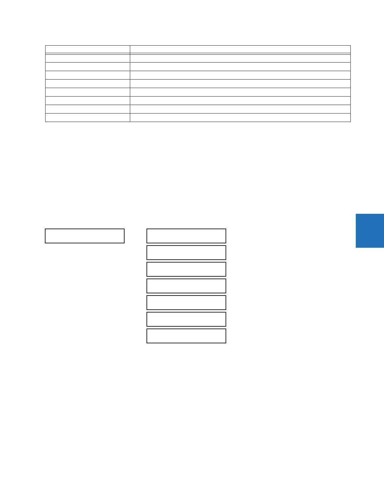
LATCH 1
LATCH 1
FUNCTION: Disabled
Range: Disabled, Enabled
LATCH 1 ID:
NV Latch 1
Range: up to 20 alphanumeric characters
LATCH 1 TYPE:
Reset Dominant
Range: Reset Dominant, Set Dominant
LATCH 1 SET:
Off
Range: FlexLogic operand
LATCH 1 RESET:
Off
Range: FlexLogic operand
LATCH 1
TARGET: Self-reset
Range: Self-reset, Latched, Disabled
LATCH 1
EVENTS: Disabled
Range: Disabled, Enabled
Unit Description