6-22 C70 CAPACITOR BANK PROTECTION AND CONTROL SYSTEM – INSTRUCTION MANUAL
METERING CHAPTER 6: ACTUAL VALUES
6
This menu displays the magnitudes of the raw differential current and compensated operating currents (in per-units of the
differential CT) for each phase.
6.4.4.5 Neutral current unbalance
ACTUAL VALUES METERING CAPACITOR BANK NEUTRAL CURRENT... NEUTRAL CURRENT UNBALANCE 1(3)
This menu displays the magnitudes of the raw neutral split-phase current and compensated operating current (in per-units
of the ground CT input).
6.4.5 Tracking frequency
ACTUAL VALUES METERING TRACKING FREQUENCY
The tracking frequency displays here. The frequency is tracked based on the selection of the reference source with the
FREQUENCY AND PHASE REFERENCE setting in the SETTINGS SYSTEM SETUP POWER SYSTEM menu. See the Power
System section of chapter 5 for details.
6.4.6 FlexElements
ACTUAL VALUES METERING FLEXELEMENTS FLEXELEMENT 1(16)
The operating signals for the FlexElements are displayed in pu values using the following definitions of the base units.
Table 6-2: FlexElement base units
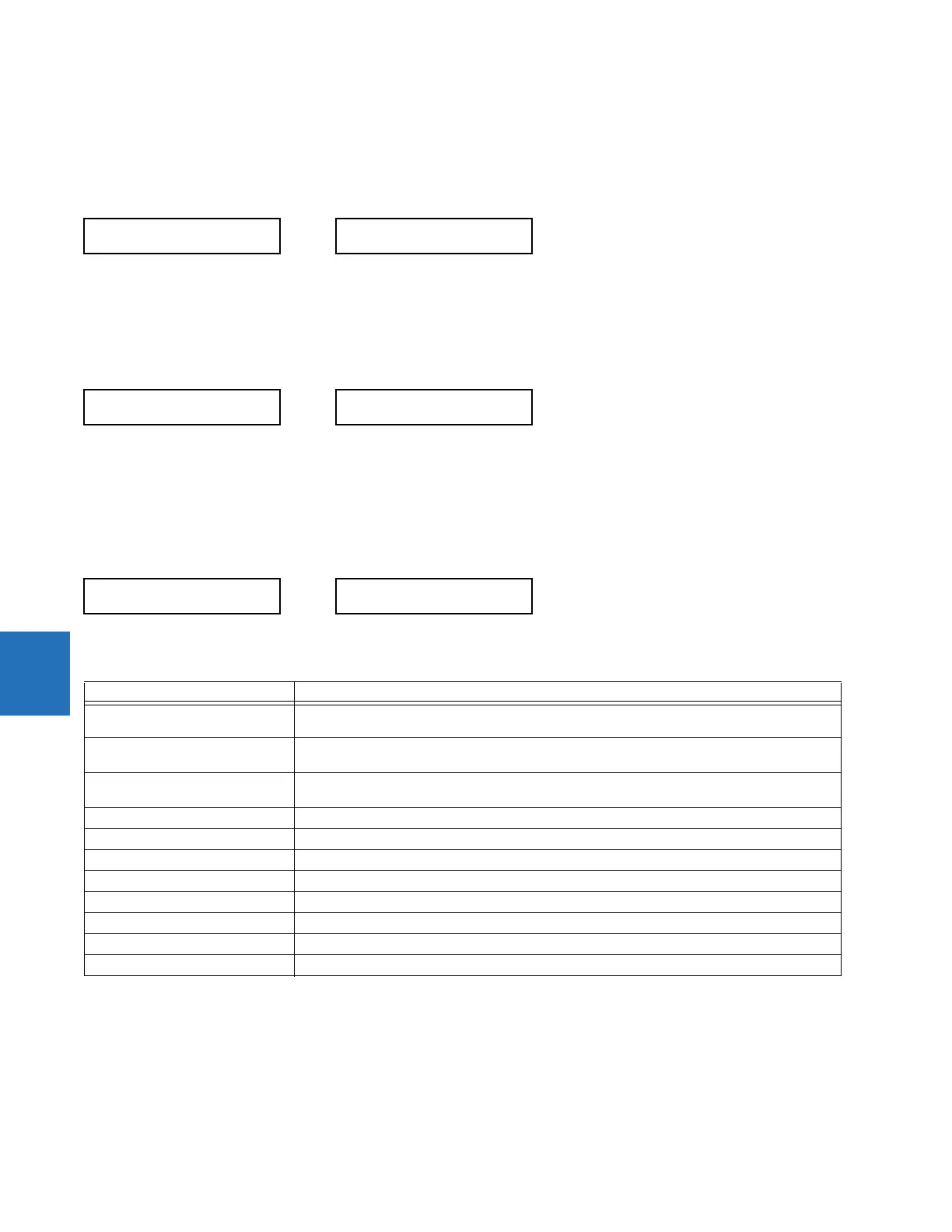
NEUTRAL CURRENT
UNBALANCE 1
Raw INsp: 0.0000 pu
Comp Iop: 0.0000 pu
TRACKING FREQUENCY
TRACKING FREQUENCY:
60.00 Hz
FLEXELEMENT 1
FLEXELEMENT 1
OpSig: 0.000
Base unit Description
BREAKER ACC ARCING AMPS
(Brk X Acc Arc Amp A, B, and C)
BASE = 2000 kA
2
× cycle
BREAKER ARCING AMPS
(Brk X Arc Amp A, B, and C)
BASE = 1 kA
2
× cycle
DCmA BASE = maximum value of the DCMA INPUT MAX setting for the two transducers configured
under the +IN and –IN inputs.
FREQUENCY f
BASE
= 1 Hz
PHASE ANGLE ϕ
BASE
= 360 degrees (see the UR angle referencing convention)
POWER FACTOR PF
BASE
= 1.00
RTDs BASE = 100°C
SOURCE CURRENT I
BASE
= maximum nominal primary RMS value of the +IN and –IN inputs
SOURCE POWER P
BASE
= maximum value of V
BASE
× I
BASE
for the +IN and –IN inputs
SOURCE THD & HARMONICS BASE = 1%
SOURCE VOLTAGE V
BASE
= maximum nominal primary RMS value of the +IN and –IN inputs