8-2 C70 CAPACITOR BANK PROTECTION AND CONTROL SYSTEM – INSTRUCTION MANUAL
ARRANGEMENT OF SHUNT CAPACITOR BANKS CHAPTER 8: APPLICATION OF SETTINGS
8
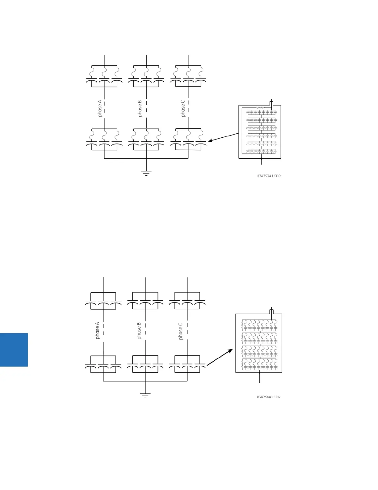
Figure 8-1: Externally fused shunt capacitor bank and capacitor unit
8.1.3 Internally fused capacitors
Each capacitor element is fused inside the capacitor unit. A simplified fuse is a piece of wire sized to melt under the fault
current, and encapsulated in a wrapper able to withstand the heat produced by the arc during the current interruption.
Upon the capacitor failure, the fuse removes the affected element only. The other elements, connected in parallel in the
same group, remain in service but with a slightly higher voltage across them.
The figure illustrates a typical capacitor bank utilizing internally fused capacitor units. In general, banks employing
internally fused capacitor units are configured with fewer capacitor units in parallel, and more series groups of units than
are used in banks employing externally fused capacitor units. The capacitor units are built larger because the entire unit is
not expected to fail.
Figure 8-2: Internally fused shunt capacitor bank and capacitor unit
8.1.4 Fuseless capacitors
A fuseless capacitor bank typically is the most prevalent design. The capacitor units in the bank are connected in series
strings between phase and neutral. The higher the bank voltage, the more capacitor elements in series.