CHAPTER 8: APPLICATION OF SETTINGS SETTINGS EXAMPLE
C70 CAPACITOR BANK PROTECTION AND CONTROL SYSTEM – INSTRUCTION MANUAL 8-15
8
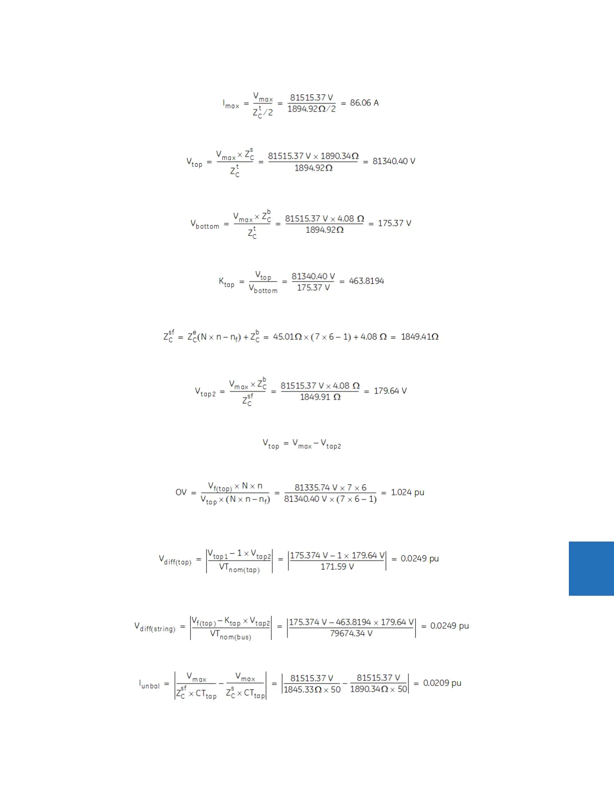
The maximum rated phase current of the healthy bank:
Eq. 8-11
The maximum rated voltage across the healthy top section:
Eq. 8-12
The maximum rated voltage across the healthy bottom section:
Eq. 8-13
The voltage distribution factor for the healthy perfectly balanced bank for the 87V-2 and 87V-3 elements:
Eq. 8-14
The impedance of the string for the failed capacitors elements (for one failed element, n
f
= 1:
Eq. 8-15
The voltage at the tap in the section with one failed capacitor element in the string:
Eq. 8-16
The voltage of the top section with one capacitor element failed:
Eq. 8-17
The overvoltage at the affected capacitors with one capacitor element failed:
Eq. 8-18
The differential voltage between two taps with one failed capacitor element in the upper string, assuming K = 1 for 87V-1,
in per-unit values is:
Eq. 8-19
The differential voltage between the bus voltage and the tap with one failed capacitor element in the upper string,
assuming K = 1, for 87V-3 in per-unit values is:
Eq. 8-20
The unbalance current in the window type CT between two strings with one failed capacitor element in the upper string:
Eq. 8-21