CHAPTER 4: INTERFACES FRONT PANEL INTERFACE
C70 CAPACITOR BANK PROTECTION AND CONTROL SYSTEM – INSTRUCTION MANUAL 4-21
4
The letters T, S, B, R, and X next to a controllable element have the following meaning. An example (TSB) is shown in the
next figure.
• T — The element is "tagged." Local and remote control of the device are inhibited, both open and close. Tripping is
unaffected unless additional logic has been configured.
• S — The position indication of the device is substituted with a manually entered value
• B — Blocking open/close command is bypassed
• R — Autoreclose is enabled and not blocked
• X — The device is out-of-service and control is not available
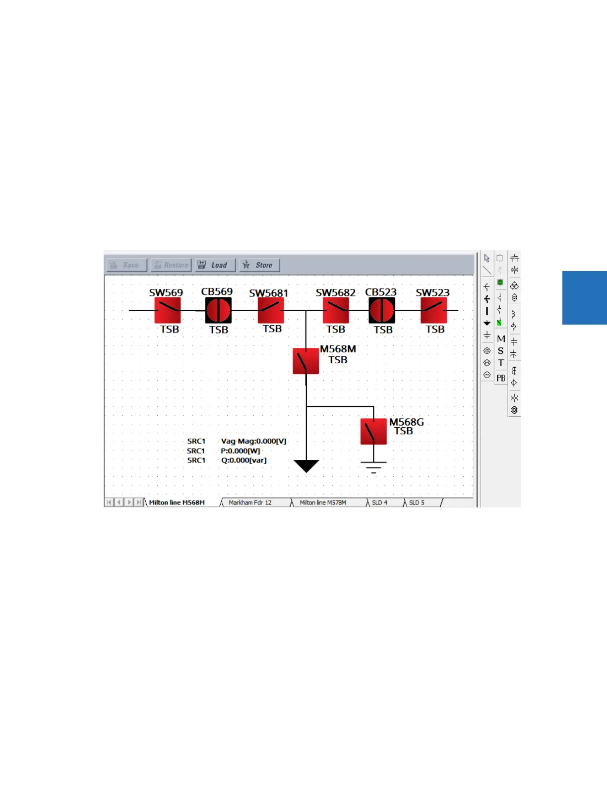
Single-line diagram example
The following example outlines how to create a circuit breaker diagram, then how to close the second circuit breaker. The
figure shows six switches (SW, M), two breakers (CB), feeder (arrow), and ground (lined arrow).
Figure 4-25: Single-line diagram of open circuit breakers
Under Settings > System Setup > Switches and Breakers, enable and name the six switches and two breakers. Switch 6,
M568G, has the A/3 Pole Opened setting on.