4-60 C70 CAPACITOR BANK PROTECTION AND CONTROL SYSTEM – INSTRUCTION MANUAL
LOGIC DIAGRAMS CHAPTER 4: INTERFACES
4
• Inputs-on the left side, which are setting and operands
• Logical gates, which is Boolean algebra to combine logical lines using AND, OR, NOT, and other gates to get a new
logical state
• Logical operators, which are timers, one-shot operations, latches, and so on
• Outputs-on the right side, which are products of the manipulations with inputs, logical gates, and logical operators to
produce new operands and define the output state of the element
True and false values are denoted by 1 and 0 respectively. A function usually is high/on/enabled when 1.
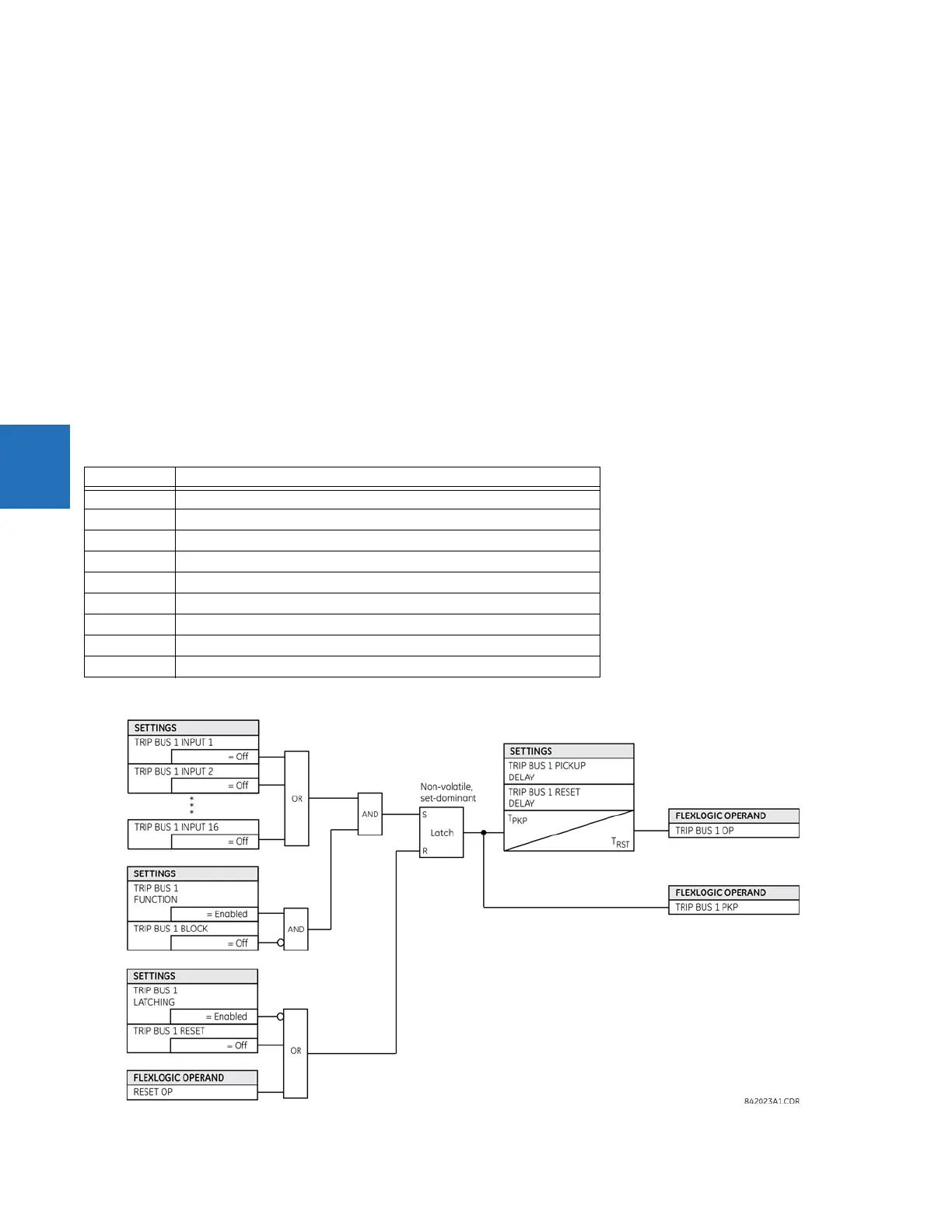
Reading from right to left in the following diagram, the TRIP BUS 1 OP and TRIP BUS 1 PKP FlexLogic operands on the right side
are triggered when either the settings or reset latch in the middle of the diagram is triggered. When this applies, the TRIP
BUS 1 OP operand is triggered after the delay set by the
TRIP BUS 1 PICKUP DELAY or TRIP BUS 1 RESET DELAY setting, while the
TRIP BUS 1 PKP operand initiates immediately. The settings or reset latch in the middle of the diagram is triggered as follows.
• For the reset, one of three conditions are required to meet the OR requirement shown at the bottom left. That is, the
TRIP BUS 1 LATCHING setting must be 0=Disabled (which is negated by the NOT function to become 1=Enabled), output
from the TRIP BUS 1 RESET FlexLogic operand must be 1, or output from the RESET OP FlexLogic operand must be 1.
• For the settings, one of 16 input conditions at the top left must be met for the OR, the
TRIP BUS 1 FUNCTION must be
Enabled, and the TRIP BUS 1 BLOCK output must output as 0, which is then negated/reversed by NOT to become 1.
Table 4-2: Logic diagram symbols
Figure 4-64: Logic diagram
Symbol Description
= Off Output from FlexLogic operand, so user-defined
= Enabled 1 = Enabled and 0 = Disabled
OR Any function input on the left side satisfies the condition
AND All functions input on the left side are required to satisfy the condition
Not. Negates/reverses the output, for example 0 becomes 1.
Connection
S, R Set, Reset
T
PKP
Timer pickup. Triggered by the settings latch in the diagram.
T
RST
Timer reset. Triggered by the reset latch in the diagram.