Home
GE
Protection Device
C70
GE C70 User Manual
4
of 1
of 1 rating
702 pages
Give review
Manual
Specs
To Next Page
To Next Page
To Previous Page
To Previous Page
Loading...
CHAPTER 5: SETTINGS
SYSTEM SETUP
C70 CAPA
CIT
OR BANK PROTECTION AND CONTROL SYSTEM – INSTRUCTION MANUAL
5-161
5
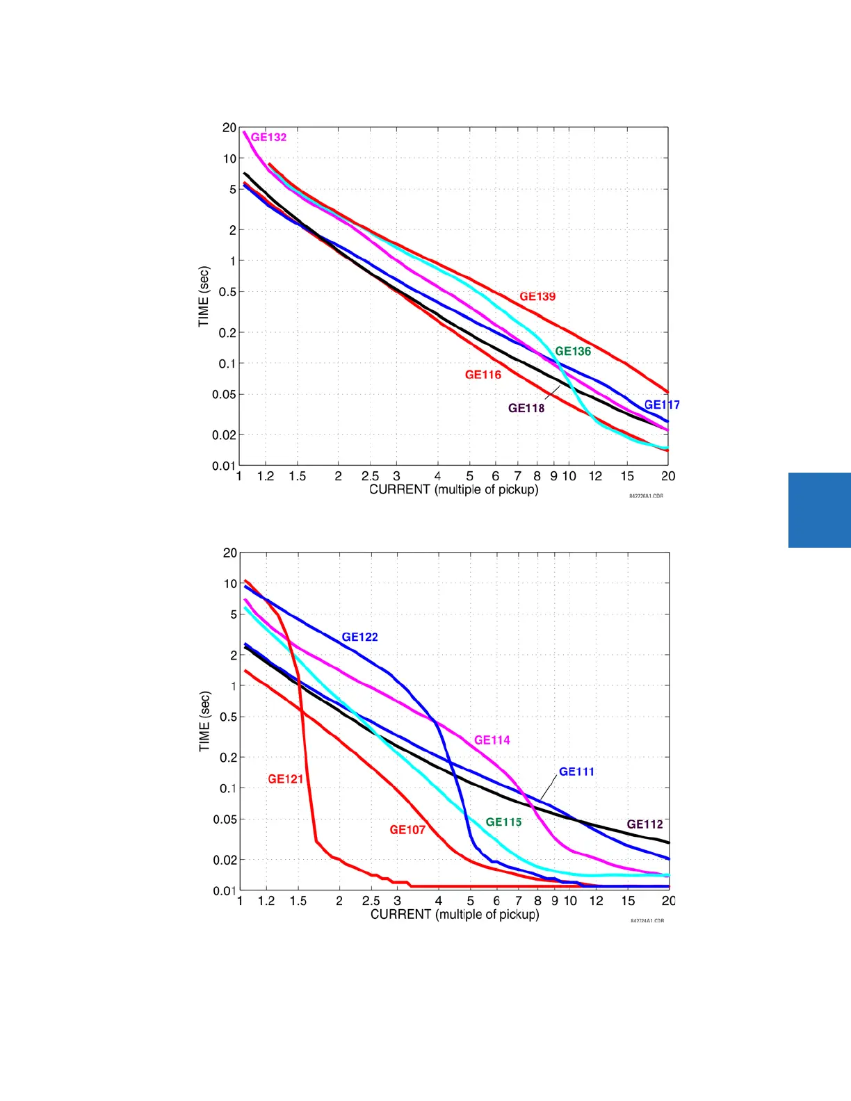
Figure 5-82: Recloser curves GE116, GE117, GE118, GE132, GE136, and GE139
Figure 5-83: Recloser curves GE107, GE
111, GE112, GE114, GE115, GE121, a
nd GE122
364
366
Table of Contents
Default Chapter
3
Table of Contents
3
1 Introduction
11
Safety Symbols and Definitions
11
General Cautions and Warnings
11
For Further Assistance
12
2 Product Description
15
Description
16
Security
17
Order Codes
22
Order Codes with Enhanced CT/VT Modules
22
Order Codes with Process Bus Modules
24
Replacement Modules
27
Signal Processing
29
UR Signal Processing
29
Specifications
31
Protection Elements
32
User-Programmable Elements
37
Monitoring
38
Metering
39
Inputs
40
Power Supply
41
Outputs
42
Communications
44
Inter-Relay Communications
45
Cybersentry Security
46
Graphical Front Panel
46
Environmental
47
Type Tests
48
Production Tests
48
Approvals
49
Maintenance
49
3 Installation
51
Unpack and Inspect
51
Panel Cutouts
52
Horizontal Units
52
Vertical Units
56
Rear Terminal Layout
61
Wiring
64
Typical Wiring
64
Dielectric Strength
65
Control Power
65
CT/VT Modules
66
Process Bus Modules
68
Contact Inputs and Outputs
69
Transducer Inputs and Outputs
81
RS232 Port
83
CPU Communication Ports
84
Irig-B
86
Direct Input and Output Communications
87
Description
87
Fiber: LED and ELED Transmitters
89
Interface
89
RS422 Interface
93
IEEE C37.94 Interface
95
Activate Relay
98
Install Software
99
Enervista Communication Overview
99
System Requirements
100
Install Software
101
Add Device to Software
102
Set IP Address in UR
103
Configure Serial Connection
108
Configure Ethernet Connection
110
Configure Modem Connection
111
Automatic Discovery of UR Devices
111
Connect to the C70
112
Connect to the C70 in Enervista
112
Use Quick Connect Via Front RS232 Port
113
Use Quick Connect Via Front USB Port
114
Use Quick Connect Via a Rear Ethernet Port
114
Set up Cybersentry and Change Default Password
115
Import Settings
116
Connect to D400 Gateway
117
Oscillography Files
117
Event Records
117
Log Files
117
Setting Files
118
4 Interfaces
119
Enervista Software Interface
119
Introduction
119
Settings Files
119
Event Viewing
120
File Support
121
Enervista Main Window
121
Protection Summary Window
122
Settings Templates
123
Secure and Lock Flexlogic Equations
127
Settings File Traceability
130
Front Panel Interface
133
Front Panel
133
Front Panel Display
135
Front Panel Navigation Keys
155
LED Indicators
156
Front Panel Labelling
161
Menu Navigation
167
Change Settings
169
View Actual Values
174
Breaker Control
175
Change Passwords
176
Invalid Password Entry
177
Logic Diagrams
177
Flexlogic Design Using Engineer
179
Design Logic
181
Send File to and from Device
191
Monitor Logic
192
View Front Panel and Print Labels
193
Generate Connectivity Report
194
Preferences
194
Toolbars
198
5 Settings
205
Settings Menu
205
Overview
208
Introduction to Elements
208
Introduction to AC Sources
209
Product Setup
211
Security
211
Display Properties
229
Graphical Front Panel
231
Clear Relay Records
243
Communications
244
Modbus User Map
311
Real-Time Clock
311
User-Programmable Fault Report
316
Oscillography
317
Data Logger
319
User-Programmable Leds
321
User-Programmable Self Tests
325
Control Pushbuttons
325
User-Programmable Pushbuttons
327
Flex State Parameters
332
User-Definable Displays
333
Direct Inputs and Outputs
335
Teleprotection
341
Installation
342
Remote Resources
342
Remote Resources Configuration
342
System Setup
344
AC Inputs
344
Power System
345
Signal Sources
346
Breakers
348
Disconnect Switch Control
354
Flexcurves
359
Flexlogic
366
Flexlogic Operands
366
Flexlogic Rules
381
Flexlogic Evaluation
381
Flexlogic Example
382
Flexlogic Equation Editor
387
Flexlogic Timers
387
Flexelements
387
Non-Volatile Latches
391
Grouped Elements
392
Overview
392
Setting Group 1
392
Phase Current
393
Neutral Current
408
Ground Current
420
Negative Sequence Current
423
Breaker Failure (ANSI 50BF)
428
Voltage Elements
438
Control Elements
455
Overview
455
Trip Bus 1
456
Setting Groups
457
Selector Switch
458
Time of Day Timers
465
Capacitor Control
467
Automatic Voltage Regulator
471
Digital Elements
475
Digital Counters
478
Monitoring Elements
480
Inputs/Outputs
496
Contact Inputs
496
Virtual Inputs
498
Contact Outputs
499
Virtual Outputs
502
Resetting
502
Direct Inputs and Outputs
503
Teleprotection
507
Transducer Inputs/Outputs
509
Dcma Inputs
509
RTD Inputs
510
Dcma Outputs
511
Testing
515
Test Mode Function
515
Test Mode Forcing
515
Force Contact Inputs
516
Force Contact Outputs
516
6 Actual Values
519
Actual Values Menu
519
Front Panel
521
Enhanced and Standard Front Panels
521
Graphical Front Panel
522
Status
522
Contact Inputs
522
Virtual Inputs
522
Rxgoose Boolean Inputs
523
Rxgoose DPS Inputs
523
Teleprotection Inputs
523
Contact Outputs
523
Virtual Outputs
524
Rxgoose Status
524
Rxgoose Statistics
524
Digital Counters
525
Selector Switches
525
Time of Day Timers
525
Flex States
526
Ethernet
526
Real Time Clock Synchronizing
526
Direct Inputs
527
Direct Devices Status
528
Teleprotection Channel Tests
528
Remaining Connection Status
528
Parallel Redundancy Protocol (PRP)
529
Txgoose Status
529
Metering
530
Metering Conventions
530
Sources
534
Capacitor Control
538
Capacitor Bank
539
Tracking Frequency
540
Flexelements
540
Rxgoose Analogs
541
Transducer Inputs/Outputs
541
Records
541
User-Programmable Fault Reports
541
Event Records
542
Oscillography
543
Data Logger
543
Breaker Maintenance
544
Product Information
545
Model Information
545
Firmware Revisions
545
7 Commands and Targets
547
Commands Menu
547
Capacitor Bank Automatic Setting
548
Virtual Inputs
552
Clear Records
552
Set Date and Time
553
Relay Maintenance
553
Security
554
Targets Menu
555
Target Messages
555
Relay Self-Tests
556
8 Application of Settings
565
Arrangement of Shunt Capacitor Banks
565
Overview
565
Externally Fused Capacitors
565
Internally Fused Capacitors
566
Fuseless Capacitors
566
Unfused Capacitors
567
Connections of Shunt Capacitor Banks
567
Grounded Wye-Connected Banks
567
Ungrounded Wye-Connected Banks
567
Delta Connected Banks
568
H-Configuration
568
Tapped Configuration
568
Protection Methods for Capacitor Banks
569
Overview
569
Capacitor Unbalance Protection
569
Protection for Rack Faults (Arc-Over Within Capacitor Banks)
574
Overvoltage
574
Overcurrent
575
Loss of Bus Voltage
575
Settings Example
575
Overview
575
VT and CT Setup
576
Source Assignment
578
Bank Unbalance Calculations
578
Bank Voltage Differential Settings
580
Bank Phase Current Unbalance Settings
582
Bank Phase Overvoltage Settings
583
Bank Phase Undervoltage Settings
584
Bank Overcurrent Protection
585
9 Theory of Operation
587
Overview
587
General Operation
587
Bank Phase Overvoltage (ANSI 59B)
587
Voltage Differential (ANSI 87V)
589
Compensated Bank Neutral Voltage Unbalance (ANSI 59NU)
593
Phase Current Unbalance (ANSI 60P)
597
Neutral Current Unbalance (ANSI 60N)
600
10 Maintenance
607
Devices with Site Targets
607
Data with Modbus Analyzer
607
General Maintenance
609
In-Service Maintenance
609
Out-Of-Service Maintenance
609
Unscheduled Maintenance (System Interruption)
609
Retrieve Files
609
Cybersentry Security Event Files
610
Convert Device Settings
611
Compare Settings
613
Compare against Defaults
613
Back up and Restore Settings
614
Copy Settings to Other Device
613
Back up Settings
614
Restore Settings
617
Upgrade Software
619
Upgrade Firmware
620
Replace Front Panel
621
Replace Module
629
Battery
630
Replace Battery for SH/SL Power Supply
630
Dispose of Battery
631
Clear Files and Data after Uninstall
635
Repairs
635
Disposal
636
Storage
636
A.1 Flexanalog Items
637
Flexanalog Items
637
B Radius Server
671
RADIUS Server Configuration
671
C Command Line
673
Command Line Interface
673
D.1 Warranty
679
Warranty
679
Revision History
679
4
Based on 1 rating
Ask a question
Give review
Questions and Answers:
Need help?
Do you have a question about the GE C70 and is the answer not in the manual?
Ask a question
GE C70 Specifications
General
Brand
GE
Model
C70
Category
Protection Device
Language
English
Related product manuals
GE 850
664 pages
GE 869
606 pages
GE D60
826 pages
GE F35
682 pages
GE 339
342 pages
GE F60
732 pages
GE 350
786 pages
GE 889
580 pages
GE M60
676 pages
GE MI-869
552 pages
GE Multilin 850
616 pages
GE MiCOM P747 Agile
458 pages