CHAPTER 5: SETTINGS FLEXLOGIC
C70 CAPACITOR BANK PROTECTION AND CONTROL SYSTEM – INSTRUCTION MANUAL 5-179
5
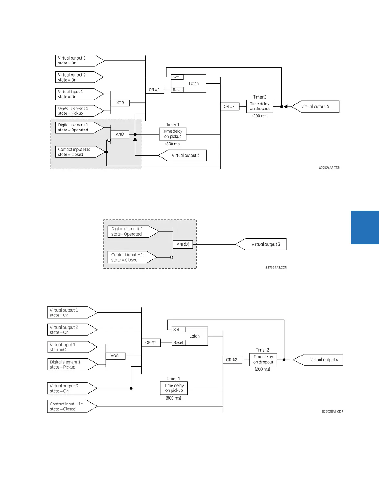
Figure 5-87: Logic example with virtual outputs
2. Prepare a logic diagram for the equation to produce virtual output 3, as this output is used as an operand in the virtual
output 4 equation (create the equation for every output that is used as an operand first, so that when these operands
are required they already have been evaluated and assigned to a specific virtual output). The logic for virtual output 3
is shown as follows with the final output assigned.
Figure 5-88: Logic for virtual output 3
3. Prepare a logic diagram for virtual output 4, replacing the logic ahead of virtual output 3 with a symbol identified as
virtual output 3, shown as follows.
Figure 5-89: Logic for virtual output 4
4. Program the FlexLogic equation for virtual output 3 by translating the logic into available FlexLogic parameters. The
equation is formed one parameter at a time until the required logic is complete. It is generally easier to start at the
output end of the equation and work back towards the input, as shown in the following steps. It is also recommended