CHAPTER 5: SETTINGS FLEXLOGIC
C70 CAPACITOR BANK PROTECTION AND CONTROL SYSTEM – INSTRUCTION MANUAL 5-181
5
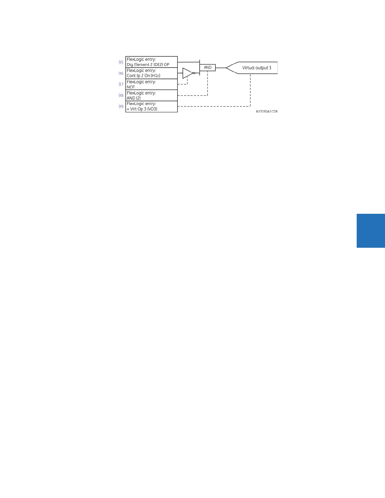
Figure 5-91: FlexLogic equation for virtual output 3
6. Repeating the process described for virtual output 3, select the FlexLogic parameters for Virtual Output 4.
– 99: The final output of the equation is virtual output 4, which is parameter “= Virt Op 4".
– 98: The operator preceding the output is timer 2, which is operand “TIMER 2". Note that the settings required for
the timer are established in the timer programming section.
– 97: The operator preceding timer 2 is OR #2, a 3-input OR, which is parameter “OR(3)”.
– 96: The lowest input to OR #2 is operand “Cont Ip H1c On”.
– 95: The center input to OR #2 is operand “TIMER 1".
– 94: The input to timer 1 is operand “Virt Op 3 On".
– 93: The upper input to OR #2 is operand “LATCH (S,R)”.
– 92: There are two inputs to a latch, and the input immediately preceding the latch reset is OR #1, a 4-input OR,
which is parameter “OR(4)”.
– 91: The lowest input to OR #1 is operand “Virt Op 3 On".
– 90: The input just above the lowest input to OR #1 is operand “XOR(2)”.
– 89: The lower input to the XOR is operand “DIG ELEM 1 PKP”.
– 88: The upper input to the XOR is operand “Virt Ip 1 On".
– 87: The input just below the upper input to OR #1 is operand “Virt Op 2 On".
– 86: The upper input to OR #1 is operand “Virt Op 1 On".
– 85: The last parameter is used to set the latch, and is operand “Virt Op 4 On".
The equation for virtual output 4 is:
[85] Virt Op 4 On
[86] Virt Op 1 On
[87] Virt Op 2 On
[88] Virt Ip 1 On
[89] DIG ELEM 1 PKP
[90] XOR(2)
[91] Virt Op 3 On
[92] OR(4)
[93] LATCH (S,R)
[94] Virt Op 3 On
[95] TIMER 1
[96] Cont Ip H1c On
[97] OR(3)
[98] TIMER 2
[99] = Virt Op 4
Now check that the selection of parameters produce the required logic by converting the set of parameters into a
logic diagram. The result is shown in the figure, which is compared to the logic for virtual output 4 diagram as a check.