5-196 C70 CAPACITOR BANK PROTECTION AND CONTROL SYSTEM – INSTRUCTION MANUAL
GROUPED ELEMENTS CHAPTER 5: SETTINGS
5
Time to assert this operand after PHASE TOC 1 operated with I
2
t curves is estimated using following formula.
Eq. 5-15
where
τ is a time constant fixed to a 10 minute value
l
PKP
is a pickup setting of TOC
l
F
is a maximum phase fault current
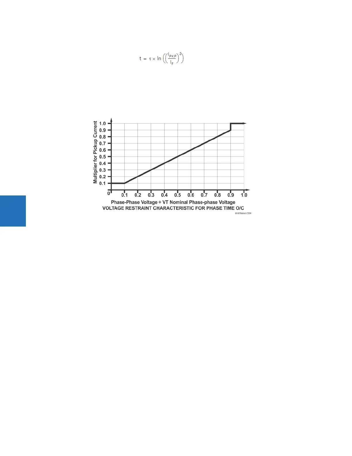
Figure 5-97: Phase time overcurrent voltage restraint characteristic
FUNCTION — This setting enables and disables the phase time overcurrent protection element.
SIGNAL SOURCE — Selects the signal source for the phase time overcurrent protection element.
INPUT — Selects how phase current input quantities are interpreted by the C70. Inputs can be selected as fundamental
phasor magnitudes or total waveform RMS magnitudes as required by the application.
PICKUP — Specifies the phase time overcurrent pickup level in per-unit values.
CURVE — Selects the time inverse overcurrent curve style.
TD MULTIPLIER — Specifies a multiple of the base curve shape specified by the CURVE setting. Programming this value to
zero results in an instantaneous response to all current levels above pickup.
RESET — The “Instantaneous” reset method is intended for applications with other relays, such as most static relays, which
set the energy capacity directly to zero when the current falls below the reset threshold. The “Timed” reset method can be
used where the relay must coordinate with electromechanical relays.
VOLTAGE RESTRAINT — Enables and disables the phase time overcurrent voltage restraint feature.
BLOCK A — Assertion of the operand assigned to this setting blocks phase A of the phase time overcurrent element.
EVENTS — Enables and disables the logging of phase time overcurrent events in the sequence of events recorder.