CHAPTER 5: SETTINGS GROUPED ELEMENTS
C70 CAPACITOR BANK PROTECTION AND CONTROL SYSTEM – INSTRUCTION MANUAL 5-203
5
The relay allows manual setting of the inherent unbalance factors, or automatically via the COMMANDS menu. For more
information, see the Application of Settings chapter.
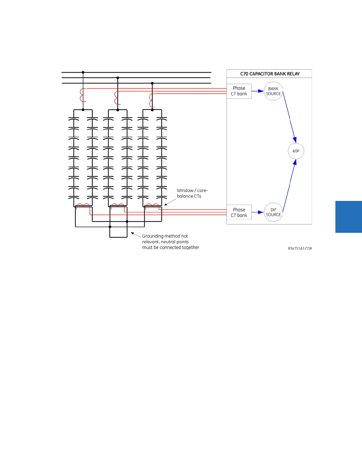
Figure 5-102: Phase current unbalance basic connections
The following settings are available for all three elements.
CUR UNBALCE 1 DIF SOURCE — Indicate signal source that signifies the differential currents between the two parallel banks.
In order to improve accuracy, a relatively low-ratio window CT can be used for instrumentation. CT primary and secondary
ratings are entered under a separate menu. Directionality of wiring these current signals is not important for proper
functioning of the feature as long as the sign of the factor compensating for the inherent unbalance is appropriate. For
ease of analysis and consistency of relay records, wire all three currents with the same polarity.
CUR UNBALCE 1 BANK SOURCE — Indicate signal source that signifies the total current of the two parallel banks. Either the
main CTs are placed in a way ensuring measurement of the total current, or the currents of individual banks are summed
externally to the relay by paralleling the main CTs, or summed up internally to the relay using the configuration
mechanism of sources. The total bank current is used for compensation for the inherent bank unbalance. CT primary and
secondary ratings are entered under a separate menu. Directionality of wiring these current signals is not important for
proper functioning of the feature as long as the sign of the factor compensating for the inherent unbalance is appropriate.
For ease of analysis and consistency of relay records, wire all three currents with the same polarity. If any of the
compensating factors is non-zero, the BANK SOURCE must have phase CT current configured for this function to run.
CUR UNBALCE 1 INHNT FACTOR A(B,C) — This setting specifies the compensating factor for the inherent unbalance between
the two banks. Normally, the compensating factors are small numbers being a ratio of the difference between the two
impedances, and the sum of the two impedances. For example, with 1% difference between the impedances, the factor is
(1-0.99)/(1+0.99) = 0.005. The sign of the compensating factor depends on the polarity of wiring the differential signals, and
on which of the two banks has the lower impedance. Quality of balancing the bank with a given value of this setting can be
viewed under the
ACTUAL VALUES menu. An auto-setting procedure is available under the COMMANDS menu to calculate the
compensating factors automatically. Setting the compensating factors to zero effectively disables the compensation and
turns this feature into a plain overcurrent element responding to the differential (split phase) currents.