CHAPTER 5: SETTINGS GROUPED ELEMENTS
C70 CAPACITOR BANK PROTECTION AND CONTROL SYSTEM – INSTRUCTION MANUAL 5-209
5
The directional unit uses the zero-sequence current (I_0) or ground current (IG) for fault direction discrimination and can
be programmed to use either zero-sequence voltage (“Calculated V0” or “Measured VX”), ground current (IG), or both for
polarizing. The zero-sequence current (I_0) must be greater than the
PRODUCT SETUP DISPLAY PROPERTIES CURRENT
CUT-OFF LEVEL
setting value and IG must be greater than 0.05 pu to be validated as the operating quantity for directional
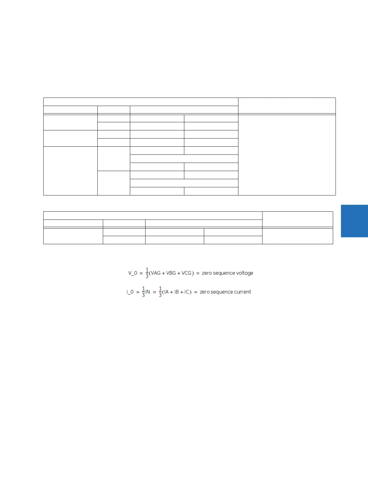
current. The following tables define the neutral directional overcurrent element. V_0 is the zero-sequence voltage, I_0 is
the zero-sequence current, ECA is the element characteristic angle, and IG is the ground current.
Table 5-33: Quantities for "calculated 3I0" configuration
Table 5-34: Quantities for "measured IG" configuration
where:
ECA = element characteristic angle
IG = ground current
Z_offset is the offset impedance, for which magnitude is the OFFSET setting and angle is the FWD ECA
When
NEUTRAL DIR OC1 POL VOLT is set to “Measured VX,” one-third of this voltage is used in place of V_0. The following
figure explains the usage of the voltage polarized directional unit of the element.
The figure shows the voltage-polarized phase angle comparator characteristics for a phase A to ground fault, with:
• ECA = 90° (element characteristic angle = centerline of operating characteristic)
• FWD LA = 80° (forward limit angle = the ± angular limit with the ECA for operation)
• REV LA = 80° (reverse limit angle = the ± angular limit with the ECA for operation)
Take the bias into account when using the neutral directional overcurrent element to directionalize other protection
elements.
Directional unit Overcurrent unit
Polarizing mode Direction Compared phasors
Voltage Forward –V_0 + Z_offset × I_0 I_0 × 1∠ECA I
op
= 3 × (|I_0| – K × |I_1|) if |I
1
| > 0.8 pu
I
op
= 3 × (|I_0|) if |I
1
| ≤ 0.8 pu
Reverse –V_0 + Z_offset × I_0 –I_0 × 1∠ECA
Current Forward IG I_0
Reverse IG –I_0
Dual, Dual-V, Dual-I Forward –V_0 + Z_offset × I_0 I_0 × 1∠ECA
or
IG I_0
Reverse –V_0 + Z_offset × I_0 –I_0 × 1∠ECA
or
IG –I_0
Directional unit Overcurrent unit
Polarizing mode Direction Compared phasors
Voltage Forward –V_0 + Z_offset × IG/3 IG × 1∠ECA I
op
= |IG|
Reverse –V_0 + Z_offset × IG/3 –IG × 1∠ECA