5-212 C70 CAPACITOR BANK PROTECTION AND CONTROL SYSTEM – INSTRUCTION MANUAL
GROUPED ELEMENTS CHAPTER 5: SETTINGS
5
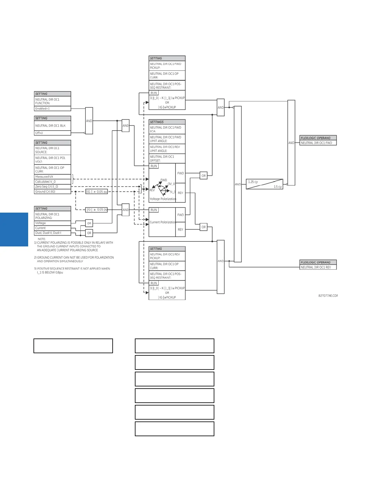
Figure 5-107: Neutral directional overcurrent logic
5.7.4.5 Neutral current unbalance (ANSI 60N, IEC PVCB/PTOC)
SETTINGS GROUPED ELEMENTS SETTING GROUP 1(6) NEUTRAL CURRENT NEUTRAL CURRENT
UNBALANCE 1(3)
NEUTRAL CURRENT
UNBALANCE 1
NTRL CUR UNBALCE 1
FUNCTION: Disabled
Range: Disabled, Enabled
NTRL CUR UNBALCE 1
BANK SOURCE: SRC 1
Range: SRC 1, SRC 2, SRC 3, SRC 4, SRC 5, SRC 6
NTRL CUR UNBALCE 1
K MAG: 0.0000
Range: 0.0000 to 0.1500 in steps of 0.0001
NTRL CUR UNBALCE 1
K ANG: 0°
Range: 0 to 359° in steps of 1
NTRL CUR UNBALCE 1
STG 1 PKP: 0.020 pu
Range: 0.001 to 5.000 pu in steps of 0.001
NTRL CUR UNBALCE 1
STG 1 SLOPE: 2.0%
Range: 0.0 to 10.% in steps of 0.1