5-214 C70 CAPACITOR BANK PROTECTION AND CONTROL SYSTEM – INSTRUCTION MANUAL
GROUPED ELEMENTS CHAPTER 5: SETTINGS
5
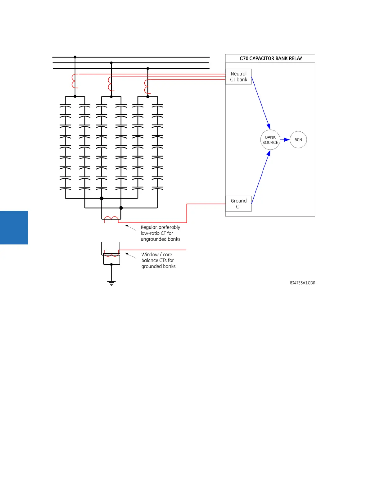
Figure 5-108: Neutral current unbalance connections
The following settings are available. They are for the neutral current unbalance 1 element. The same descriptions apply to
the neutral current unbalance 2 and 3 elements.
NTRL CUR UNBALCE 1 BANK SOURCE — This setting indicates the signal source that signifies the split-phase neutral current in
its ground current channel. At minimum the ground channel of this source must be set. If the factor compensating for
inherent bank unbalance is set above zero signalling the intent of using the compensation, the phase currents of this
source must be configured as well. Without the phase currents configured under this source, the function would run only if
the magnitude of the inherent unbalance factor is set to zero.
To improve accuracy, a relatively low-ratio window CT can be used for instrumentation of the split-phase neutral current,
and be wired to a 1 A or even sensitive ground relay input for extra sensitivity. CT primary and secondary ratings are
entered under a separate menu. Directionality of wiring of the split-phase current is not important for proper functioning of
the feature as long as the angle of the factor compensating for the inherent unbalance is set appropriately.
NTRL CUR UNBALCE 1 K MAG — This setting defines magnitude of the factor compensating for the inherent unbalance of the
bank. Under balanced conditions, the amount of the spill current measured in the neutral connection between the banks is
proportional to the positive-sequence component of the total current of the two banks. This setting defines the magnitude
of the proportionality factor. Quality of balancing the bank with a given value of this setting can be viewed under
ACTUAL
VALUES
menu. An automatic setting procedure is available via the COMMANDS menu to calculate the compensating factor
automatically. Setting the compensating factor to zero effectively disables the compensation. If further the slope is set to
zero as well, this feature becomes a plain overcurrent element responding to the neutral split-phase current.