CHAPTER 5: SETTINGS GROUPED ELEMENTS
C70 CAPACITOR BANK PROTECTION AND CONTROL SYSTEM – INSTRUCTION MANUAL 5-239
5
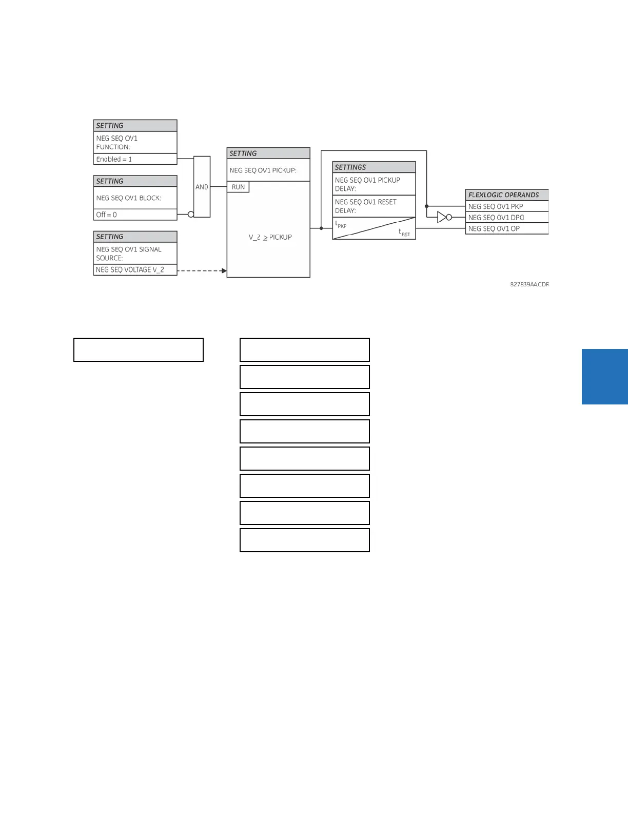
Use the negative-sequence overvoltage element to detect loss of one or two phases of the source, a reversed phase
sequence of voltage, or a non-symmetrical system voltage condition.
Figure 5-126: Negative-sequence overvoltage logic
5.7.8.6 Auxiliary overvoltage (ANSI 59X, IEC PTOV)
SETTINGS GROUPED ELEMENTS SETTING GROUP 1(6) VOLTAGE ELEMENTS AUXILIARY OV1(3)
The C70 contains one auxiliary overvoltage element for each VT bank. This element is intended for monitoring overvoltage
conditions of the auxiliary voltage. The nominal secondary voltage of the auxiliary voltage channel entered under
SYSTEM
SETUP AC INPUTS VOLTAGE BANK X5 AUXILIARY VT X5 SECONDARY
is the per-unit (pu) base used when setting the
pickup level.
AUXILIARY OV1
AUX OV1
FUNCTION: Disabled
Range: Disabled, Enabled
AUX OV1 SIGNAL
SOURCE: SRC 1
Range: SRC 1, SRC 2, SRC 3, SRC 4, SRC 5, SRC 6
AUX OV1 PICKUP:
0.300 pu
Range: 0.004 to 3.000 pu in steps of 0.001
AUX OV1 PICKUP
DELAY: 1.00 s
Range: 0.00 to 600.00 s in steps of 0.01
AUX OV1 RESET
DELAY: 1.00 s
Range: 0.00 to 600.00 s in steps of 0.01
AUX OV1 BLOCK:
Off
Range: FlexLogic operand
AUX OV1 TARGET:
Self-reset
Range: Self-reset, Latched, Disabled
AUX OV1 EVENTS:
Disabled
Range: Disabled, Enabled