CHAPTER 5: SETTINGS GROUPED ELEMENTS
C70 CAPACITOR BANK PROTECTION AND CONTROL SYSTEM – INSTRUCTION MANUAL 5-249
5
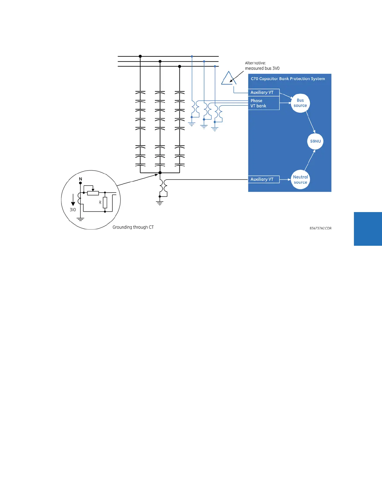
Figure 5-132: Neutral voltage unbalance basic connection
The following settings are available for all three neutral voltage unbalance elements.
NTRL VOL UNBAL 1 NTRL SOURCE — Indicates signal source that signifies the neutral-point voltage of the protected bank.
This single-phase voltage is to be configured under the auxiliary VT channel. The VT ratio and secondary nominal voltage
are set under separate menu. Nominal voltage of this auxiliary channel becomes a unit (1 pu) for the pickup settings of this
function.
NTRL VOL UNBAL 1 BUS SOURCE — Indicates signal source that signifies the bus voltages of the bank. This source must have
the phase voltages configured in order to facilitate compensation for the inherent unbalance of the bank. The zero-
sequence voltage required for system unbalance compensation can be derived from the phase voltages, or delivered to
the relay from an external source, typically a broken-delta VT (the selection is controlled by the next setting of this function).
In the latter case, the 3V0 signal is expected and must be wired and configured under the auxiliary voltage channel of this
source. This 3V0 voltage must be labelled as “Vn” under the VT configuration. The VT ratio and secondary nominal voltage
are set under separate menu. Phase voltages of this source must be connected in wye for the function to operate. The
function uses several voltages potentially produced by VTs of different ratios and nominal secondary values. The relay
scales all the signals automatically for meaningful calculations.
NTRL VOL UNBAL 1 BUS 3V0 — Specifies the source of the bus zero-sequence voltage required for system unbalance
compensation. If set to “Calculated”, the relay would derive the zero-sequence voltage as a vector sum of the three phase
voltages and will run the function if voltage in all three phases is greater than 0.25 pu. If set to “Measured”, the relay
expects the 3V0 signal (not a V0) to be wired to the relay under the auxiliary channel of the bus source, and labelled as “Vn”.
In this case, the voltage check to run this function is not performed.
NTRL VOL UNBAL 1 GROUND — Selects the grounding arrangement of the bank. For ungrounded banks, set it to “VT
(ungrnd)”. When the bank neutral is solidly grounded through the CT with a resistor in the CT secondary, set it as “CTxR
(grnd)”.